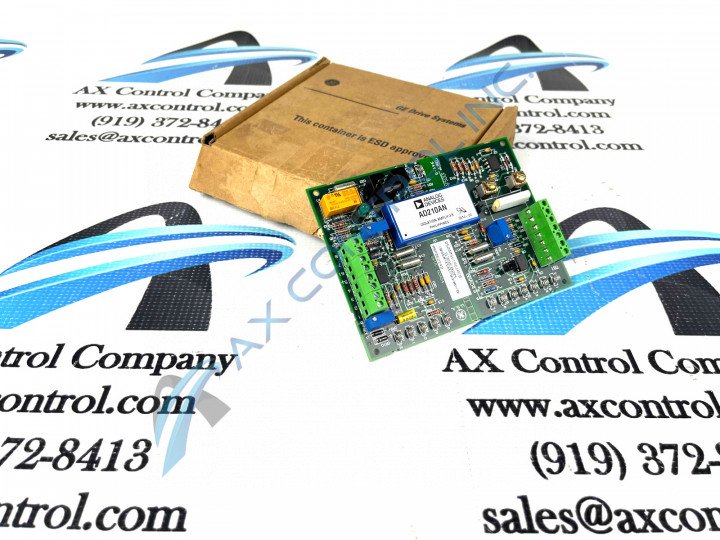
About the DS200SVIAG1ACB
This DS200SVIAG1ACB GE Shunt Isolator Board is a General Electric product originally manufactured with a specific placement in their Mark V Turbine Control System Series, which as indicated by its name, has specific applications in the control and management systems of wind, gas, and steam turbine automated drive assemblies. The Mark V Series that this DS200SVIAG1ACB printed circuit board belongs to one of the latest General Electric product series to incorporate their patented style of Speedtronic technoogy into its products, although the Mark V Turbine Control System Series is also considered a legacy series due to its eventual discontinuation by the General Electric manufacturer. This DS200SVIAG1ACB printed circuit board is better-definable within the Mark V Series and related automated drive assemblies as a Shunt Isolator Board; the functional description that it is referred to as in original Mark V Turbine Control System Series instructional manual materials. This DS200SVIAG1ACB printed circuit board or PCB for short is not the original product with its functionality to exist within the bounds of the Speedtronic Mark V Series, however; the original is the DS200SVIAG1 Shunt Isolator Board notably missing all three of this DS200SVIAG1ACB product offering's three significant product revisions.
Hardware Tips and Specifications
This DS200SVIAG1ACB printed circuit board introduces many crucial hardware elements and element specifications to gain full series functionality as a Shunt Isolator Board specifically. The GE Shunt Isolator Board DS200SVIAG1ACB features 2 terminal blocks. One terminal block contains 7 signal wire terminals and one contains 8 signal wire terminals. The GE Shunt Isolator Board DS200SVIAG1ACB also contains multiple test points, 2 jumpers, and 1 LED, which has been introduced into its assembly for fault detection purposes. The jumpers on the DS200SVIAG1ACB board are labeled JP1 and JP2; these jumpers are used to configure the board to process information as required by its greater Mark V Series automated drive. Some of the jumpers cannot be changed and are instead used only by the factory during the manufacturing process. In that case, the jumper is moved to test a particular process. Then, it is moved back to configure the board to the supported jumper position. This DS200SVIAG1ACB PCB is a Mark V Series product offering that does not offer a whole lot of original instructional manual materials online for research purposes. With that being said, the DS200SVIAG1ACB functional product number itself is a good source of relevant SVIA Shunt Isolator Board hardware information. The DS200SVIAG1ACB functional product number begins with the DS200 series tag detailing this DS200SVIAG1ACB product's normal Mark V Series assembly and domestic location of manufacture. This is followed in the DS200SVIAG1ACB number by an instance of the SVIA functional product acronym, which is itself followed by the G1 series grouping tag revealing the DS200SVIAG1ACB PCB's normal style of PCB protective coating and group one Mark V Series grouping. the end of the DS200SVIAG1ACB functional part number contains three alphanumeric digits, revealing this DS200SVIAG1ACB board's three significant product revisions and their grades.
The terminal blocks in the assembly of this DS200SVIAG1ACB PCB can connect to a maximum of 15 signal wires. When you replace the GE Shunt Isolator Board DS200SVIAG1ACB it is vital that you connect the signal wires to the same terminals on the replacement board. To ensure that you connect the signal wires to the appropriate terminals you must follow some guidelines, as introduced in original DS200SVIAG1ACB instructional manuals. Examine the defective board when it is still mounted in the drive and note where the signal wires are attached. Pin to the signal wires the ID of the terminal it is attached to. Next, use a screwdriver to free the signal wire from the terminals. When you have mounted the new board in the rack, loosen the screws in the terminals and insert the bare copper end into the appropriate terminal. Tighten the connection and pull on the wire to test the connection, and the installation process should be complete.


