About the DS200TBCAG1A
The DS200TBCAG1A Mark V Series printed circuit board from General Electric was originally produced with the intended functionality as a RTD Termination Module, although original General Electric instructional manual materials do describe this once-revised product offering as an Analog I/O Terminal Board as well. This DS200TBCAG1A RTD Termination Module's singularly-revised status means that it does not exist as the original General Electric RTD Termination Module within their Mark V Series; that would be the DS200TBCAG1 RTD Termination Module missing the singular revision.
Hardware Tips and Specifications
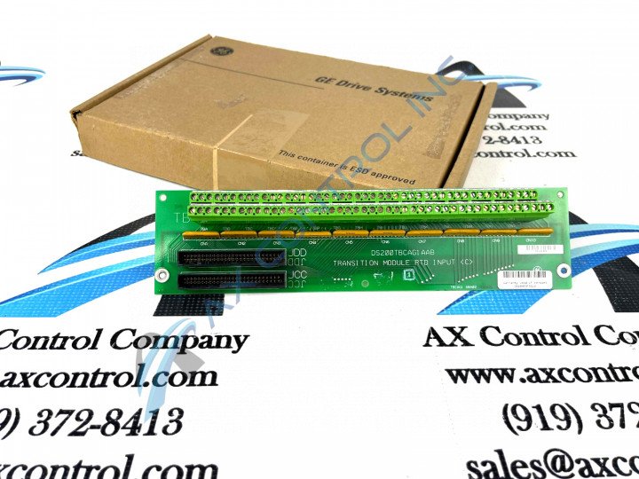
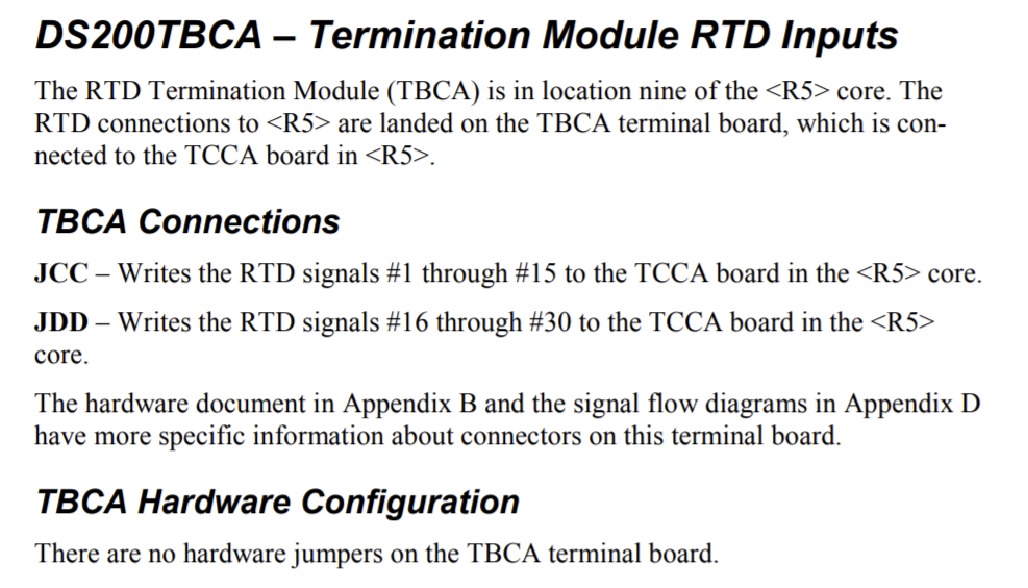
This DS200TBCAG1A RTD Termination Module, which considered a Mark V Series module product, is not determined to possess any sort of special assembly version outside of its revised status. The GE Analog I/O Terminal Board DS200TBCAG1A features 2 blocks of 90 signal wire terminals and 2 50-pin connectors. One 50-pin connector is labeled JDD and the other is labeled JCC. All of the various hardware elements included in the internal assembly of this DS200TBCAG1A RTD Termination Module should receive some form of protection from this Mark V Series product's normal style of printed circuit board coating, which is a rudimentary base layer of protection applied to the base board and various hardware elements of this DS200TBCAG1A printed circuit board on a functional priority basis.
50-pin connectors are attached to ribbon-type cables that require some special consideration before you connect or disconnect them to prevent damage to the ribbon cable, as introduced in original General Electric instructional manual materials. To disconnect a ribbon cable do not touch the ribbon portion of the cable; hold the connector portion and remove it from the connector on the board, while using your other hand to support the board and keep the board from moving or bending under the pressure. There are potentially multiple signal wires connected to the terminals and so it is best practice to designate where to connect each signal wire by labeling each wire with the ID of the terminal before you disconnect it. With as many as 180 signal wires it is important to eliminate the opportunity for error that would increase the downtime for the drive. Each signal is made up of a few strands of copper wire that might be inadvertently disconnected from the connector. Because of the weight of the drive, and the large number of signal cables, the drive is connected to the board rack through the use of 4 screws. Make sure you utilize all 4 screws during normative installation to support the weight of the board and prevent the board from moving inside the drive.


