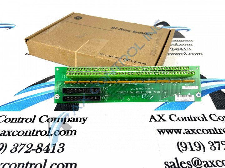
About the DS200TBCAG1AAB
This DS200TBCAG1AAB printed circuit board product offering from General Electric was originally manufactured for placement in the Mark V Turbine Control System Series. The Mark V Series that this DS200TBCAG1AAB printed circuit board or PCB for short belongs to has specific applications in the control and management systems of popular and compatible wind, steam, and gas turbine control and management systems.
This DS200TBCAG1AAB PCB's Mark V Series still seems to attract a niche demand on the figurative automated industrial marketplace, as it exists as one of the lastly-developed product series to make use of the patented Speedtronic control system technology first introduced with the rollout of the primary Mark I Series in the later 1960s.
Hardware Tips and Specifications
As with any Mark V Series printed circuit board made available to our new and extended reconditioned inventory here; this DS200TBCAG1AAB PCB's intended functional role is introduced with its normal Mark V Series assembly's adoption of a specialized series of functionality-inducing hardware components and component specifications. The GE Analog I/O Terminal Board DS200TBCAG1AAB features 2 blocks of 90 signal wire terminals and 2 50-pin connectors. The replacement of the GE Analog I/O Terminal Board DS200TBCAG1AAB is a straightforward procedure provided you can move the signal wires from the terminal blocks on the old board to the terminal blocks on the replacement board. This DS200TBCAG1AAB PCB is not the originally-developed product of its specific Mark V Series functionality; that would be the DS200TBCAG1 parent Analog I/O Terminal Board missing this DS200TBCAG1AAB Device's three significant product revisions. This DS200TBCAG1AAB PCB, as with any Mark V Series product, utilizes several specific connector styles to establish important connections with other Mark V Series products. Some of this DS200TBCAG1AAB PCB's original instructional manual-listed connectors include:
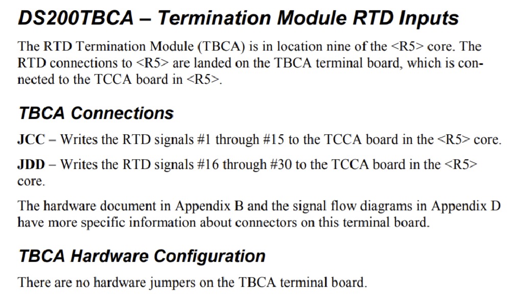
- The JCC TCCA Board 1-15 RTD SIgnals R5 Core Connectors
- The JDD TCCA Board 16-30 RTD SIgnals R5 Core Connectors
Only a qualified servicer can perform this task due to the high energy contained in the drive when it is connected to electrical current. Disconnect the drive from the power source which is installed to meet local and national electrical standards. The drive is connected to a power supply that converts AC power to the DC power used to run the drive. It is also important to locate the emergency power shut off equipment connected to the drive. In case of an emergency it is important to have at least two individuals working on the replacement. If an emergency situation occurs, help is available to call for emergency assistance or shut off the power using the emergency shutoff device. First, if possible remove the defective board with the signal wires still attached and place it on a clean and stable surface with an EDS protective surface underneath it. For example, a flat static protective bag. Wear a wrist strap and place the replacement board next to the old board. And one at a time move the signal wires from the old board to the new board. According once again to the DS200TBCAG1AAB Instructional Manual attached in the manuals tab above, this DS200TBCAG1AAB PCB does not feature any manually-moveable hardware jumper or other piece of customizable hardware in its normal Mark V Series assembly.


