DS200TBQBG1A

    Varying star amount pictures Varying star amount pictures Varying star amount pictures Varying star amount pictures Varying star amount pictures
  • 4.73 (15)
  • Click a star to rate this product
    Varying star amount pictures Varying star amount pictures Varying star amount pictures Varying star amount pictures Varying star amount pictures
  • 4.73 (15)
  • Click a star to rate this product
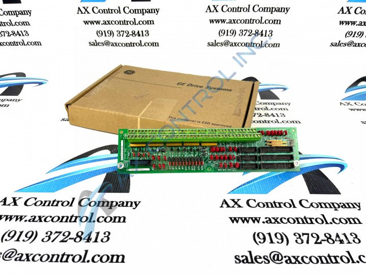
This DS200TBQBG1A General Electric Input Termination Module was manufactured specifically for the Mark V Series of turbine control systems.

AVAILABILITY:

IN STOCK
SHIPS TODAY

Sell Surplus: Have a DS200TBQBG1A to sell? Sell Now
Exchange Credit: Learn more about our exchange credit program
  • Part Number: DS200TBQBG1A
  • SKU: DS200TBQBG1AGBTC
  • Manufacturer: GE Boards & Turbine Control
  • Series: Mark V DS200

DS200TBQBG1A Technical Specifications

Manufacturer GE General Electric
Series Mark V
Part Number DS200TBQBG1A
Functional Description Input Termination Module
Functional Acronym TBQB
PCB Coating Normal Coating
Functional Revision 1 A

About the DS200TBQBG1A

This DS200TBQBG1A circuit board product offering from the industry-respected General Electric retailer is considered quite the valuable presence to its Mark V product series, as it is deemed as functional both as an Analog Termination Board and as an Input Termination Module in original General Electric instructional manual materials. Before making a final purchase decision on this DS200TBQBG1A Input Termination Module, it is crucial to be aware of the fact that this Mark V Series product offering exists as a revised version of a pre existing General Electric printed circuit board product; modifying the DS200TBQBG1 Input Termination Module by use of a singular, A-rated functional product revision.

Hardware Tips and Specifications

Like many to all of the other product offerings in GE's Mark V Series, this DS200TBQBG1A Input Termination Board makes use of several product-specific hardware inclusions and specifications to reach its intended series functionality. The GE RST Analog Termination Board DS200TBQBG1A features 2 terminal blocks, with each block contains 77 terminals for signal wires. The GE RST Analog Termination Board DS200TBQBG1A also contains 15 jumpers, 3 34-pin connectors, and 3 16-pin connectors. The opportunities for diagnosing the board if you suspect a problem are limited with this product specifically due to the lack of test points and indicator LEDs. Test points give a means of attaching the specific circuits on the board to a testing device and identifying problems, while LEDs typically provide a means for gaining an indication of the general health and processing activity in the board. While limited in its number of standard diagnostic components, the DS200TBQBG1A's Mark V Series drive contains some diagnostic tools that when run, produce a report of all the functions of the drive and can help diagnose a problem with the board. The tools reside in the programmable read only memory (PROM) on the drive and are available for use from the control panel.

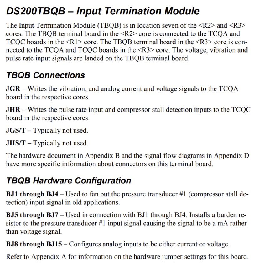
Several different connector types have been adopted into the assembly of this DS200TBQBG1A Input Termination Board for Mark V Series interfacing possibilities. The primary connector utilized in the assembly of this Mark V Series product has to be cited as the JGR connector, which writes any vibration, analog current or voltage signal needed for respective cores within the related Mark V Series TCQA board assembly. Some of the other connectors utilized by this General Electric Input Termination Board include the JHR connector, the JGS/T connector, and the JHS/T connector.

Frequently Asked Questions about DS200TBQBG1A

What are DS200TBQBG1A's termination signals?
DS200TBQBG1A has 4 termination signals. DS200TBQBG1A has pulse rate inputs, DS200TBQBG1A has compressor discharge transmitters, DS200TBQBG1A has DC voltage inputs, and DS200TBQBG1A has a vibration transducer.
Where is DS200TBQBG1A located in the core?
When DS200TBQBG1A is in the < R > core, DS200TBQBG1A is in location 7.
What are the jumpers on DS200TBQBG1A?
DS200TBQBG1A's BJ1 through BJ4 jumpers are used to fan out the pressure transducer #1 input signal in old applications. Jumpers BJ5 through BJ7 on DS200TBQBG1A are used in connection with BJ1 through BJ4. These jumpers on DS200TBQBG1A install a burden resistor to the pressure transducer #1 input signals causing the signal to be a milliamp rather than a voltage signal. Jumpers BJ8 through BJ15 on DS200TBQBG1A configure analog inputs to be either current or voltage on DS200TBQBG1A.

Reviews For DS200TBQBG1A

Internal Review
(5.0)

This DS200TBQBG1A Input Termination Module is a crucial member of its attributed Mark V Series of turbine control systems. This is reflected in many hardware specifications applicable to this DS200TBQBG1A printed circuit board, from its inclusion of a reinforcing A-rated functional product revision to its reference by multiple monikers in original Mark V Series instructional documentation. While many connectors have been adopted into the assembly of this DS200TBQBG1A Input Termination Module, its JGS/T and JHS/T connectors are typically unused. - AX Control Lead Technician

Repair Services For DS200TBQBG1A

Type Lead Time Price Action
Repair Service 1-2 weeks $425

Our highly skilled technicians can repair your DS200TBQBG1A. All of our repairs come with a 3 Year AX Control Warranty. Please contact us for additional information about our repair process. To receive the repair pricing and lead time listed above please process your repair order via our website. The following repair options may be available upon request:

  • 48-72hr Rush Repair
  • Detailed Repair Reports
  • AX Control Certificate of Warranty

AX Control Warranty Info

All products we sell are backed by our unparalleled warranty. A warranty certificate will be provided with your order upon request.
All PLCs, HMIs, and Turbine Control Boards: 3 Years
All AC/DC and Servo Drives: 2 Years
All Motors: 1 Year
Learn More

DS200TBQBG1A Manuals, White Papers, Data Sheets, and Troubleshooting