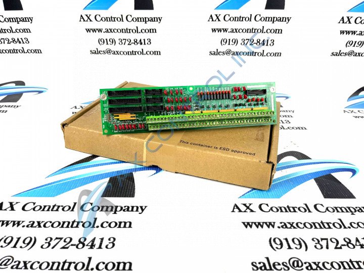
About the DS200TBQBG1ACB
This DS200TBQBG1ACB printed circuit board product offering from General Electric was designed and manufactured to exist as an Analog Termination Board within their Mark V Turbine Control System Series. The Mark V Series that this DS200TBQBG1ACB printed circuit board or PCB for belongs to has specific applications in the management and control systems of popular and compatible wind, steam, and gas turbine automated drive assemblies.
This DS200TBQBG1ACB PCB's greater Mark V Series has still been able to attract something of a high demand on the figurative automated industrial marketplace, as it is one of the lastly-developed GE Mark product series to incorporate their patented Speedtronic control system technology across a range of PCB offerings.
Hardware Tips and Specifications
The GE RST Analog Termination Board DS200TBQBG1ACB features 2 terminal blocks. Each block contains 77 terminals for signal wires. The GE RST Analog Termination Board DS200TBQBG1ACB also contains:
- 15 jumpers
- 3 34-pin connectors
- 3 16-pin connectors
The 154 terminals are used to connect copper signal wires to the board. The signal wires are connected to other components and boards in the drive and the board receives the signals for processing. The signal wires also transmit some signals to other boards and components in the drive. The information that is supplied with the original board from the factory documents the signals that connect to each terminal. When you install the original board you can use that information to know which terminal to connect each signal wire.
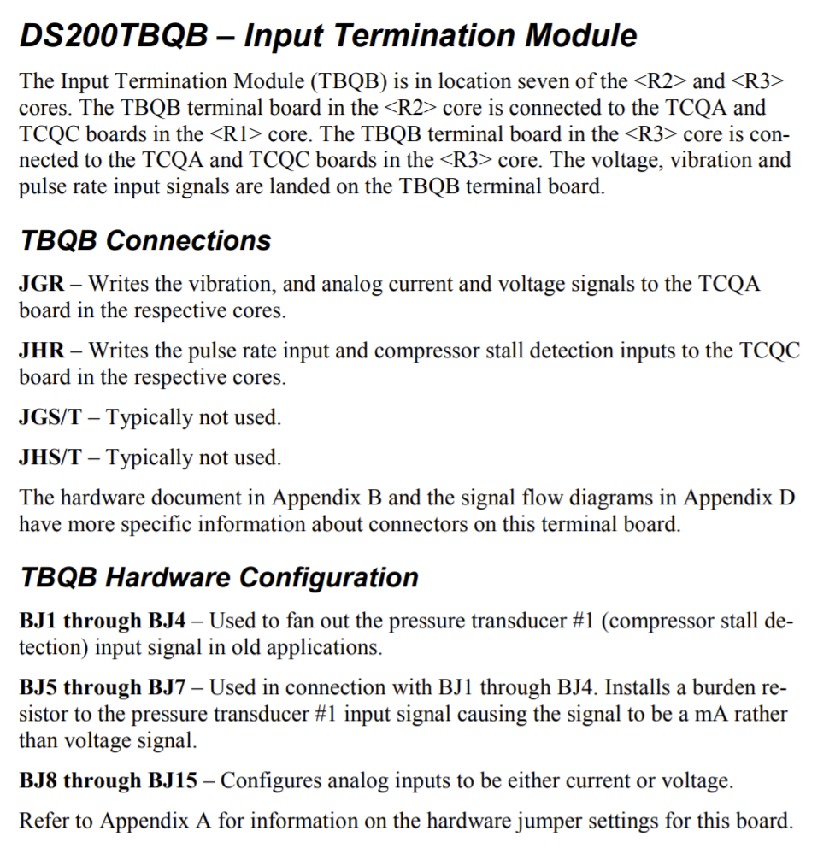
While this DS200TBQBG1ACB printed circuit board is definable in its own right as an Analog Termination Board, it is not the originally-developed product of this specific Mark V Series functional role; that would be the DS200TBQBG1 parent Analog Termination Board notable missing this DS200TBQBG1ACB PCB's three significant product revisions. This DS200TBQBG1ACB printed circuit board, while existing as a highly-revised Mark V Series PCB model, also is revered within industrial circles for its bold customization strategy, which incorporates several jumpers into the internal assembly of this DS200TBQBG1ACB product. Each of the jumpers in this DS200TBQBG1ACB Analog Termination Board's assembly is accompanied by a factory-printed nomenclature label containing the BJ tag dictating a berg-type jumper component. The BJ1-BJ4-labeled jumpers in this DS200TBQBG1ACB PCB are used to fan out a pressure transducer, while the BJ5-BJ7-labeled jumpers installs a burden resistor for said pressure transducer. Finally, this DS200TBQBG1ACB product's BJ8-BJ15 jumpers are responsible for analog input configuration.
One terminal block is assigned ID TB1. The other terminal block is assigned ID TB2. Within each terminal block, every terminal is assigned a numerical ID. So, to identify a specific terminal refer to the terminal block ID and the numerical value for the terminal. For example TB1 66 refers to terminal 66 on terminal block 1. When you are preparing to replace the board, use the terminal IDs to know where to connect the signal wires on the replacement board. Write the IDs on masking tape or a tag and stick them to the signal wires. Use a screwdriver to release them from the terminals. Then, insert the bare copper end of the signal wire into the terminal of the replacement board and tighten the screws to secure it. Each of the specific connectors allowed to exist within the bounds of this DS200TBQBG1ACB product's normal Mark V Series assembly should be accompanied by their own factory-printed nomenclature label as dictated in the DS200TBQBG1ACB instructional manual embedded above in our handy manuals tab.
Some of this DS200TBQBG1ACB PCB's connectors include:
- the JGQ TCQA Board Various Signals Connector
- the JHR TCQC Board Pulse Rate and Detection Signals Connector
- the JGS/T Connector
- the JHS/T Connector
Each of the previously-listed connectors in this DS200TBQBG1ACB PCB's normal Mark V Series assembly has been named through a unique combination of their respective factory-printed nomenclature labels, their Mark V Series compatible products, and finally the specific signals they were designed to transmit. This DS200TBQBG1ACB PCB's JGS/T and JHS/T Connectors have not been named as such as they purely exist as vestigial structures not meant to be accessed during normative used of the DS200TBQBG1ACB PCB.


