About the DS200TBQCG1
This DS200TBQCG1 Analog Input/Milliamp I/O Termination Module from General Electric was originally manufactured by General Electric, for placement specifically in their Mark V Turbine Control System Series. As you can probably tell based off of its full extended series name, the Mark V Series that this DS200TBQCG1 printed circuit board or PCB for short belongs to has identifiable applications in the management and control systems of popular and compatible wind, gas, and steam turbine automated drive assemblies. This DS200TBQCG1 PCB's greater Mark V Series, while possessing potential alternative energy applications, has to be treated as a now-obsolete legacy product series, as its manufacture was discontinued by General Electric in one of the many years following its initial release. With this being true, this DS200TBQCG1 Analog Input/Milliamp I/O Termination Module's greater Mark V Series is still a desirable General Electric product series as it exists as one of the final GE product series to make use of the patented Speedtronic control system technology first embraced with the release of the Mark I Series in the mid to later 1960s. This DS200TBQCG1 PCB is the original product of its functionality designed and produced by General Electric, as evidenced by its DS200TBQCG1 functional product number's lack of any trailing, revision-indicating digits.
Hardware Tips and Specifications
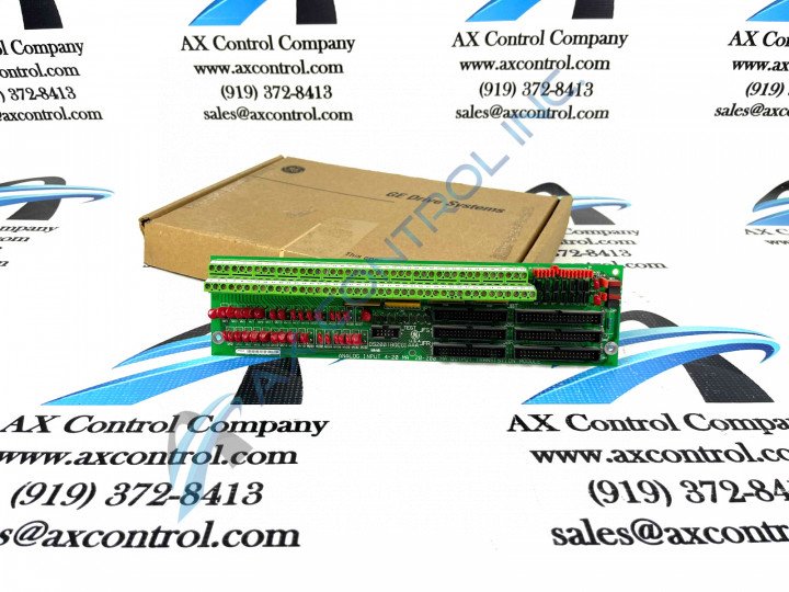
As with any General Electric Mark V Turbine Control System Series product offered for repair or replacement here, this DS200TBQCG1 PCB's intended functionality is introduced with its normal Mark V Series assembly's acceptance of a specific series of functionality-inducing hardware components and component specifications. The GE RST Analog Termination Board DS200TBQCG1 features 2 terminal blocks. Each block contains 83 terminals for signal wires. The GE RST Analog Termination Board DS200TBQCG1 also contains 15 jumpers, 3 40-pin connectors, and 3 34-pin connectors. The GE RST Analog Termination Board DS200TBQCG1 is 11.25 inches in length and 3 inches in height. It also contains one screw hole in each corner for attaching the board in the rack located inside the drive. Use care when you remove the screws because a lost screw might fall on a board and cause an electrical short that leads to a fire or electrical burn. It might also jam in the moving parts which will damage the parts or cause the drive to fail. Instead, use one hand to turn the screwdriver and the other hand to hold the screws after they are loosened. Save them in a location where they will not be disturbed or lost. Then, retrieve them to secure the replacement board. If washers were also used with the defective board, insert them with the screws when you install the replacement board.
Space on the board is devoted to the terminal blocks which supply the means for receiving signals from other boards installed in the drive. The terminals blocks also enable the board to transmit signals and information to other boards. Before you connect a signal wire to the terminal, you must strip approximately one half inch of insulation from the wire. This provides the means for an electrical connection to be made between the terminal and the signal wire. While this DS200TBQCG1 printed circuit board's various installation and replacement procedures are certainly important to adhere to, their presence on this DS200TBQCG1 personalized product page is truly more reminiscent of this DS200TBQCG1 PCB's lack of originally-printed instructional manual materials online. One hardware specification that is revealed in existing instructional documentation is the various connectors in the assembly of this DS200TBQCG1 PCB. Some of these connectors include:
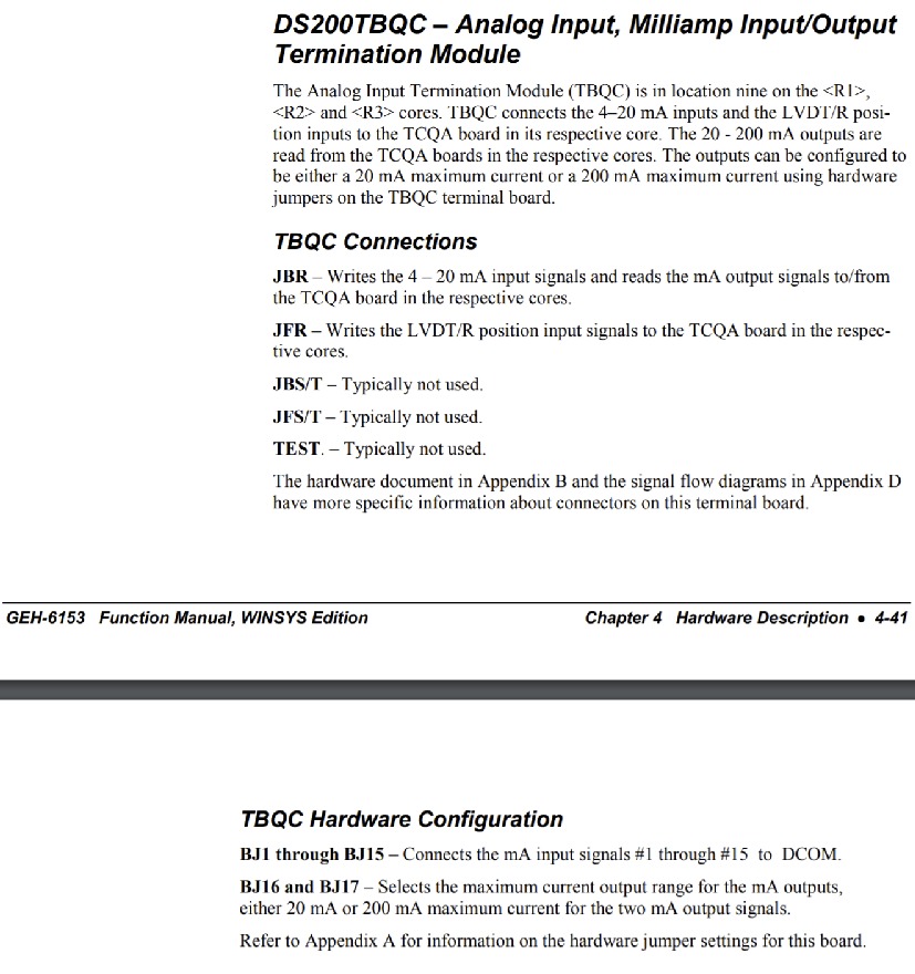
- The JBR TCQA Board Input and Output Signals Connector
- The JFR TCQA Board LVDT/R Position Input Signals Connector
- The JBS/T Connector
- The JFS/T Connector
- The TEST Connector
All of the previously-listed connectors in the normal Mark V Series assembly of this DS200TBQCG1 product offering have been named through an amalgamation of their specific factory-printed nomenclature labels, their Mark V Series compatible products, and finally the types of signals that they were designed to transmit in the Mark V Series automated drive assembly. This DS200TBQCG1 Analog Input/Milliamp I/O Termination Module's JBS/T, JFS/T, and TEST connectors have not been named as such as, according to the above-attached DS200TBQCG1 Analog Input/Milliamp I/O Termination Module instructional manual, these specific connectors solely exist as vestigial structures not meant to be accessed at all during normative functioning of the DS200TBQCG1 PCB. Generally, voltage suppression and limitation in the assembly of this DS200TBQCG1 product offering would be handled by its Mark V Series-standardized selection of voltage-limiting hardware components such as various rectifiers, capacitors, and diodes, as well as its thick, rudimentary layer of normal-style PCB surface coating.


