About the DS200TBQCG1AAA
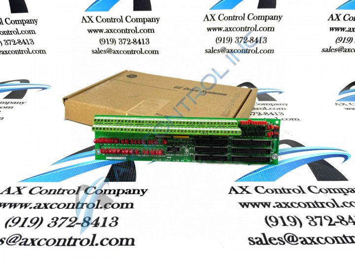
This DS200TBQCG1AAA General Electric printed circuit board is a Mark V Turbine Control System Series product with a normal assembly version but a complicated intended functionality within said Mark V Series, as alluded to earlier. This DS200TBQCG1AAA printed circuit board is referred to by its official functional description as an Analog Input Milliamp Input/Output Termination Module or Analog Input Milliamp I/O Termination Module for short, although some fringe General Electric and Mark V Series instructional manual materials may condense its functional description to that of a GE RST Analog Termination Board. This DS200TBQCG1AAA printed circuit board or PCB for short is not the original Analog Input Milliamp I/O Module that was manufactured for the Mark V Turbine Control System Series; that would be the DS200TBQCG1 parent printed circuit board missing this DS200TBQCG1AAA PCB's three significant product revisions.
Hardware Tips and Specifications
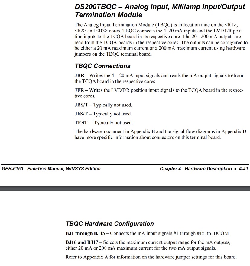
The GE RST Analog Termination Board DS200TBQCG1AAA features two terminal blocks. Each block contains eighty-three terminals for signal wires. The GE RST Analog Termination Board DS200TBQCG1AAA also contains 15 jumpers, three 40-pin connectors, and three 34-pin connectors. The jumpers enable the servicer to modify the behavior of the board to meet the exact requirements of the drive operation. The 3-pin jumper is easy to move from the default position to the alternate position. Use your forefinger and thumb to remove the jumper from the default position. Then align the jumper over the alternate pins and press the jumper into place. For example, if pins one and two are the default position in a 3-pin jumper, insert the jumper over pins two and three to use the alternate position. Some jumpers on the DS200TBQCG1AAA unit are for use by the factory only and cannot be changed. Typically the alternate position is for use at the factory for quality control testing purposes only. When you replace the board, first move the jumpers on the replacement board to match the positions on the defective one. Jumpers are not the only hardware element of note incorporated into the internal assembly of the DS200TBQCG1AAA Analog Input Milliamp I/O Termination Module. As once again described in original Mark V Turbine Control System instructional manual documentation, this DS200TBQCG1AAA printed circuit board utilizes several different relevant Mark V Series connector types in its assembly, including:
- The JBR TCQA Board Input Signal Connector
- The JFR TCQA Board LVDT/R Position Signal Connector
- The JBS/T Connector
- The JFS/T Connector
- The TEST Connector
Both the JBR and JFR DS200TBQCG1AAA PCB Connectors mentioned above are defined in terms of their intended application and use within the assembly of this DS200TBQCG1AAA printed circuit board. The three remaining JBS/T, JFS/T, and TEST Connectors listed above are only accompanied by the factory-printed nomenclature used to identify them on the surface of this DS200TBQCG1AAA PCB's base circuit board, as these specific connectors typically go unutilized during normative use of the DS200TBQCG1AAA printed circuit board and greater Mark V Series automated drive assembly.


