About the DS200TBQEG1B
This DS200TBQEG1B printed circuit board product offering from General Electric, as explained above, was originally manufactured for placement in their Mark V Turbine Control System Series. As you likely have been able to deduce based off of its full extended series name, the Mark V Series that this DS200TBQEG1B printed circuit board belongs to has specific applications in the management and control systems of popular and compatible wind, gas, or steam turbine automated drive assemblies. While this DS200TBQEG1B printed circuit board or PCB for short's greater Mark V Series does have some originally-intended applications in relatively new, alternative energy applications, it is still generally considered a now-obsolete legacy product series as its was discontinued for production in one of the many years following its initial General Electric series release. While this DS200TBQEG1B PCB's greater Mark V Series is generally obsolete, it is still something of a highly-acclaimed and sought after product series, as it exists as one of the final General Electric Mark product series to incorporate the company's famed Speedtronic control system technology into its various offerings. While this DS200TBQEG1B printed circuit board is definable as a LM6000 Analog Termination Module in its own right, the originally-produced device of this specific Mark V Series functionality is the DS200TBQEG1 parent LM6000 Analog Termination Module missing this DS200TBQEG1B PCB's singular, B-rated functional product revision.
Hardware Tips and Specifications
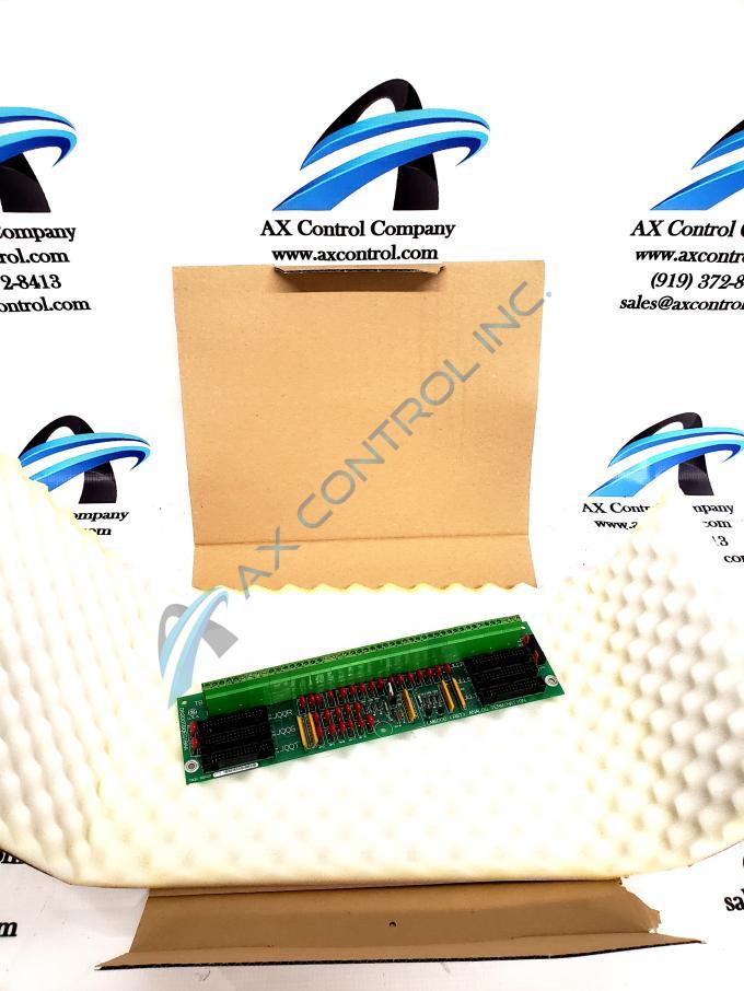
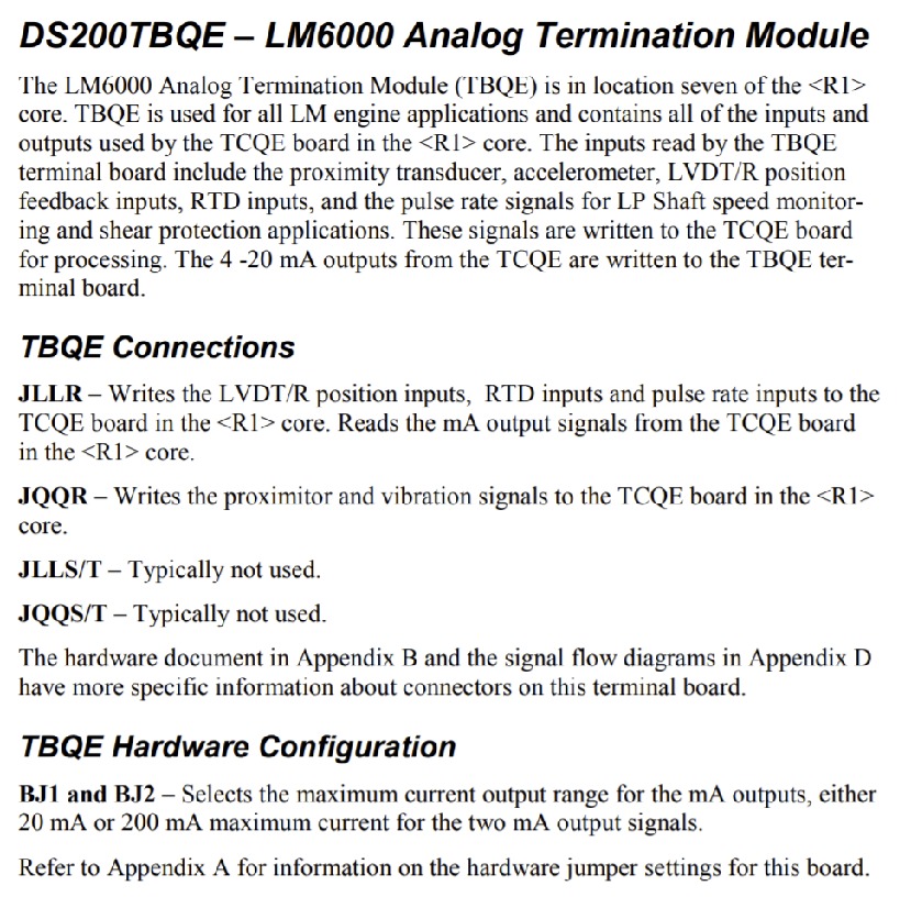
As with any Mark V Series product available to our new and reconditioned inventory here, this DS200TBQEG1B PCB's intended Mark V Series functional role is introduced with its internal assembly's adoption of a unique series of hardware components and component specifications. The GE RST LM6000 Analog Board DS200TBQEG1B features 2 terminal blocks. Each block contains 95 terminals for signal wires. The GE RST LM6000 Analog Board DS200TBQEG1B also contains 2 jumpers, and 6 34-pin connectors. The 34-pin connectors have IDs associated with them on the surface of the board. One group of 34-pin connectors are JQQR, JQQS, and JQQT. Another group of 34-pin connectors are JLLR, JLLS, and JLLT. Before you remove the ribbon cables from the 34-pin connectors it is beneficial to stick labels on the ribbon cables that indicate where the ribbon cable is connected. This helps the installer avoid mistakes when connecting the cables on the replacement board. Generally, voltage suppression and limitation in the assembly of this DS200TBQEG1B LM6000 Analog Board is handled through its internal assembly's acceptance of Mark V Series-standardized voltage-limiting hardware components such as rectifiers, capacitors, diodes, and even specialized integrated circuits. Luckily for the research purposes of this DS200TBQEG1B personalized product page here, this DS200TBQEG1B PCB's various connectors have been explained in detail in the DS200TBQEG1B instructional manual embedded in the manuals tab above for your convenience. Some of this DS200TBQEG1B PCB's various Mark V Series connectors include:
- The JLLR TCQE Board Various Input Signals Connector
- The JQQR TCQE Board Proximitor and Vibration Signals Connector
- The JLLS/T Connector
- The JQQS/T Connector
Each of the above-listed connectors in the normal assembly of this DS200TBQEG1B Device have been named through a combination of their individual factory-printed nomenclature labels, their Mark V Series compatible products, and finally the specific signals they connect for in the Mark V Series automated drive assembly. This DS200TBQEG1B PCB's JLLS/T and JQQS/T Connectors have not been named as such as they solely exist as vestigial structures not meant to be accessed during any normative functionality of this DS200TBQEG1B printed circuit board. It is also important to notice how the ribbon cables are routed inside the drive. Space is limited inside the cabinet and cable routing will allow for proper airflow which helps cool the heat-generating components in the cabinet. The drive is designed so that cool air enters the drive at the bottom and draws heat from the components as it rises. At the top of the drive it exits as hot air. The second benefit of proper cable routing is in keeping power cables away from signal wires and ribbon cables. The power cables are known to interfere with signal-carrying cables, if they are routed close together in a drive. Due to the weight of the terminal blocks and the associated signal wires the board is attached to the board rack inside the drive with 5 screws. The 6 ribbon cables attached to the 6 34-pin connectors contributes to the weight of the board.


