About the DS200TCCAG1B
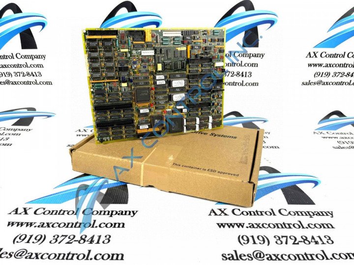
This DS200TCCAG1B printed circuit board from General Electric, as mentioned above, is a product offering originally created to exist as a member of the Mark V Series of turbine control systems and turbine control system component products. The Mark V Series that this DS200TCCAG1B PCB belongs to is considered a legacy General Electric product series, as it has since been discontinued for production by its original manufacturer. This DS200TCCAG1B printed circuit board is definable as a Common Analog IO Board, the original functional product description that it is referred to as in pertinent Mark V Series and General Electric instructional manual materials. While this DS200TCCAG1B printed circuit board does have functionality as a Common Analog I/O Board within its greater Mark V Series, it is not the original Common Analog I/O Board manufactured by General Electric; as that would be this DS200TCCAG1B device's DS200TCCAG1 parent printed circuit board missing its B-rated functional product revision.
Hardware Tips and Specifications
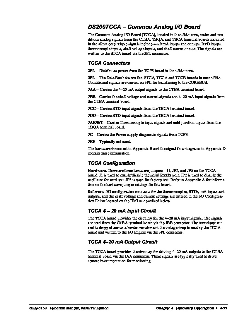
Luckily enough for our research purposes, this DS200TCCAG1B Common Analog I/O Board is a well-documented product in original General Electric instructional documentation. The GE I/O TC2000 Analog Board DS200TCCAG1B features one 80196 microprocessor and multiple PROM modules. It also contains one LED and 2 50-pin connectors, wtih the LED being visible from the side view of the DS200TCCAG1B board. The IDs for this TCCA PCB's 50-pin connectors are JCC and JDD. The GE I/O TC2000 Analog Board DS200TCCAG1B also is populated with a programmable logic device and three manually-moveable hardware jumpers. When you replace the board, typically the site will install a replacement that is exactly like the original board. In this way, the drive will perform the same as before the replacement board was installed. Several different styles of Mark V Series connectors are included in the assembly of this DS200TCCAG1B product for the maximizing of its interfacing potential. Some of these connectors include:
- The 2PL TCPS Board Power Distribution Connector
- The 3PL STCA Board COREBUS Conditioned Signal Connector
- The JAA CTBA Board 4-20 mA Output Signal Connector
- The JBB CTBA Board 4-20 mA Current Signal Connector
- The JCC and JDD TBCA Board RTD Input Signal Connectors
- The JAR/S/T TBQA Board Terminal Input Signal Connector
- The JC TCPS Board Power Supply Diagnostic Signal Connector
- The JEE Connector
As you have probably noticed, all of the above connectors available to the assembly of this DS200TCCAG1B printed circuit board have been named using a combination of their factory-printed nomenclature labels, functionality to the DS200TCCAG1B board, and other Mark V Series product compatibilities. The simply-named JEE Connector posited above is missing a full connector description as it typically goes unused during normative function of this DS200TCCAG1B Common Analog I/O Board. Moving past this DS200TCCAG1B product's connector types, one will encounter three total manually-moveable hardware jumpers, as explained before. Each of these jumpers is accompanied by its own factory-printed nomenclature label, just like the DS200TCCAG1B PCB's connectors, and each jumper selects for a different application to the DS200TCCAG1B Common Analog I/O Board. The J1-labeled jumper in this DS200TCCAG1B PCB's assembly is used for the enabling or disabling of this DS200TCCAG1B PCB's serial RS232 port. The JP2-labeled jumper in this DS200TCCAG1B PCB's assembly is used for the selection of oscillator for card test settings. Finally, the remaining JP3 jumper in this Mark V Series product offering's assembly is used for factory testing purposes only, and should not be accessed during normative functioning of the DS200TCCAG1B PCB and greater Mark V Series drive assembly.
This DS200TCCAG1B product offering, as dictated once again in the above-available instructional manual materials, is offered with a series of specialized circuits installed in its normal Mark V Series assembly in order to introduced its intended General Electric functionality. The various circuits that this DS200TCCAG1B device utilizes includes its TCCA RTD Circuit, its Thermocouple Circuit, and finally its Shaft Monitoring Circuit. The descriptions of these various DS200TCCAG1B Board circuits in the manual documentation above reveals the fact that this DS200TCCAG1B device is considered to interface with several important other Mark V Turbine Control System Series products, including but not limited to the TBQA Terminal Board, the TBCA Terminal Board, and the CTBA Terminal Board; all of which should be available to our extended inventory here across a variety of various new and reconditioned product qualities.


