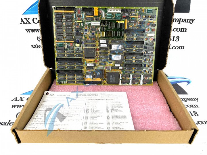
About the DS200TCCAG1BAA
This particular DS200TCCAG1BAA printed circuit board product offering was originally, as discussed just above, manufactured by General Electric, specifically for placement in their Mark V Turbine Control System Series. As you may have been able to tell based off of its full extended series name, the Mark V Series that this DS200TCCAG1BAA PCB belongs to has specific applications in the management and control systems of popular and compatible wind, gas and steam turbine automated drive assemblies. This DS200TCCAG1BAA product offering's greater Mark V Series is not a currently-manufactured General Electric mark product series, as its production was discontinued in one of the many years following its release due to obsolescence. This DS200TCCAG1BAA PCB's greater Mark V Series, while now obsolete as a legacy product series from General Electric, is still something of an esteemed product series, as it is one of the final General Electric Mark product series to make use of their patented Speedtronic control system technology first introduced alongside the rollout of the Mark I Series in the later 1960s. This DS200TCCAG1BAA PCB is not the originally designed or developed product by General Electric of its specific functional role; that would be the DS200TCCAG1 parent TC2000 I/O Analog Board missing all three of this DS200TCCAG1BAA device's three significant product revisions.
Hardware Tips and Specifications
This DS200TCCAG1BAA printed circuit board's intended TC2000 I/O Analog Board functionality is introduced with its normal Mark V Series assembly's acceptance of a unique series of hardware components and component specifications. The GE I/O TC2000 Analog Board DS200TCCAG1BAA features one 80196 microprocessor and multiple programmable read only memory (PROM) modules. It also contains one LED and 2 50-pin connectors. The LED is visible from the side view of the board. The IDs for the 50-pin connectors are JCC and JDD. The PROM modules on the GE I/O TC2000 Analog Board DS200TCCAG1BAA store instructions and firmware used by the microprocessor and programmable logic device. The information is embedded on the PROMs and can erased and a newer version stored on the PROMs. As with any Mark V Series PCB offered here, this DS200TCCAG1BAA product offering belongs to a specific Mark V Series subseries. It can be inferred that this DS200TCCAG1BAA product offering belongs to the Mark V Series' TC2000 subseries, given the insertion of the TC2000 tag in this DS200TCCAG1BAA PCB's functional description. Luckily for the purposes of this DS200TCCAG1BAA personalized product page, many of this DS200TCCAG1BAA Analog Board's originally-introduced performance specifications and dimensions have been introduced in the DS200TCCAG1BAA instructional manual above, identified primarily through their individual factory-printed nomenclature labels. Some of this DS200TCCAG1BAA PCB's connectors include:
- The 2PL TCPS Board Power Distribution Connector
- The 3PL STCA, TCCA, and TCCB Boards Data Bus Conditioned Signals Connector
- The JAA CTBA Terminal Board 4-20 mA Output Signals Connector
- The JBB CTBA Terminal Board 4-20 mA Input Signals Connector
- The JCC TBCA Terminal Board RTD Input Signals Connector
- The JDD TBCA Terminal Board RTD Input Signals Connector
- The JAR/S/T TBQA Terminal Board Input Signals Connector
- The JC TCPS Board Power Supply Diagnostic Signals Connector
- The JEE Connector
Each of the above-listed connectors in the assembly of this DS200TCCAG1BAA Mark V Series product offering have been named through a combination of their factory-printed nomenclature labels, their specific Mark V Series compatible products, and finally their specific signals that they are intended to transmit. This DS200TCCAG1BAA PCB's JEE connector has not been named as such as it exists as a vestigial structure meant to go un-accessed during normative functionality of the DS200TCCAG1BAA Board and its greater Mark V Series automated drive assembly. The PROM modules are removable from the sockets that are integrated on the board. To remove a PROM module, insert a flat-bladed screwdriver under one end of the module and gently lift up the screwdriver and the module will pop up. Then, insert the screwdriver on the other end of the module and perform the same action. Immediately place the module in a static protective bag. To install a PROM module, align the module with the socket and avoid touching the pins on the module. Press down on the module to install it. Always wear an EDS protective device, like a wrist strap because the modules are sensitive to static. The information on them can be corrupted or destroyed. To ensure the replacement board processes the same as the formerly used board, remove the modules from the old board and install them on the new board. In this way, the instructions and firmware code will be the same.


