About the DS200TCCAG2A
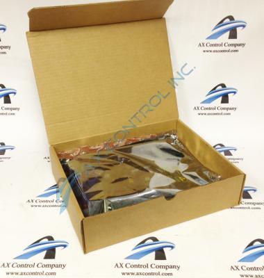
As with any General Electric Mark V Series product, this DS200TCCAG2A Common Analog I/O Board was manufactured using multiple product-specific hardware components; contributing towards its intended functionality as a Common Analog I/O Board. Fortunately for our purposes, this DS200TCCAG2A Common Analog I/O Board can additionally be considered a well-documented General Electric product offering, as it is detailed in product-specific instructional manual materials.
Hardware Tips and Specifications
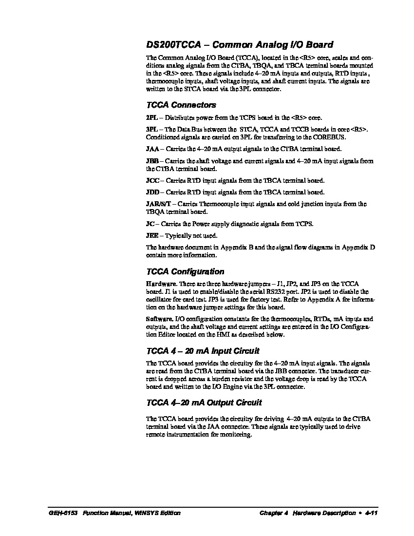
The GE I/O TC2000 Analog Board DS200TCCAG2A features one 80196 microprocessor and multiple PROM modules. It also contains one LED and 2 50-pin connectors. The LED is visible from the side view of the board. The IDs for the 50-pin connectors are JCC and JDD. The GE I/O TC2000 Analog Board DS200TCCAG2A also is populated with 5 34-pin connectors. Both the 50-pin and the 34-pin connectors use ribbon cables to connect to the rest of the DS200TCCAG2A board's assembly. Because of the potential for multiple 34-pin ribbon cables that could be connected to the new board, it is important to know where they connect when the new board is installed. Another consideration with the ribbon cables inherent to this DS200TCCAG2A Common Analog I/O Board is the proper handling technique when you disconnect them from the board. Ribbon cables have minimal support between the connector and the cable attached to them; with this in mind it is easy to pull the wires out of the connector if you tug the cable out of the connector on the board. To avoid that problem, only pull the cable out by holding the connector at the end of the ribbon cable, before gently pulling it out of the connector on the board. Adding to our ribbon cable problem here is that fact that the ribbon cable is comprised of multiple individual strands of copper wire; without taking the ribbon cable apart it is impossible to know if the connections are intact.
The ribbon cables and connectors adopted by this DS200TCCAG2A Common Analog I/O Board are not the only hardware elements present in its assembly. This DS200TCCAG2A Common Analog I/O Board additionally makes use of three total manually-moveable hardware jumpers; included in its assembly for different purposes. The JP1-labeled jumper present in this PCB's assembly is responsible for disabling of the RS-232 serial communications port. The JP2-labeled jumper present in the assembly of the DS200TCCAG2A I/O Board can disable this device's oscillator for card test. Finally, the JP3 jumper included with the DS200TCCAG2A Common Analog I/O Board is included for factory testing purposes only.


