About the DS200TCCBG1A
This DS200TCCBG1A TC2000 Analog Board was originally manufactured to exist as a member of General Electric's Mark V Series of turbine control systems. The Mark V Series is something of an aptly-named General Electric product series, as it exists possessing specific applications in the management and control systems of compatible, popular gas and steam turbine control and management systems. This DS200TCCBG1A TC2000 Analog Board is actually more accurately describable through its true functional description as a Common Extended Analog IO Board. The IO acronym in this functional description points to this DS200TCCBG1A printed circuit board's specific role as an Input/Output Board within the Mark V Series. While pertinent to some newer-developed turbine-minded applications, the Mark V Series that this DS200TCCBG1A PCB and other products here belong to has to be considered an obsolete product series as a whole, as it is truthfully a legacy product series discontinued for manufacture due to retailer-identified functional series-wide obsolescence in one of the years beyond its initial rollout.
Hardware Tips and Specifications
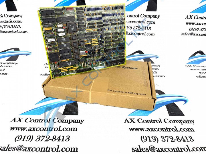
The GE I/O TC2000 Analog Board DS200TCCBG1A features one 80196 microprocessor and multiple PROM modules. It also contains one LED and 2 50-pin connectors, with the LED is visible from the side view of the board. The IDs for the 50-pin connectors used in the assembly of this DS200TCCBG1A board are JCC and JDD. The DS200TCCBG1A board also is populated with 5 34-pin connectors. The IDs for the five connectors are JAA, JBB, JAT, JAS, and JAR. Because the board contains multiple 34-pin connectors it is important to record where the ribbon cables are connected before you disconnect them. It is important to get the drive back online as quickly as possible and doing that requires making the right signal connections when you first replace the board and restart the drive. You might not know you have made the wrong connections until you have restarted the drive and find that the right signals are not being transmitted or received by the board. In that case, you can shutdown the drive and reconnect the ribbon cables. To disconnect the cables, avoid pulling the ribbon cable from the ribbon section of the cable. This will pull the fine copper strands out of the connector in a safe manner.
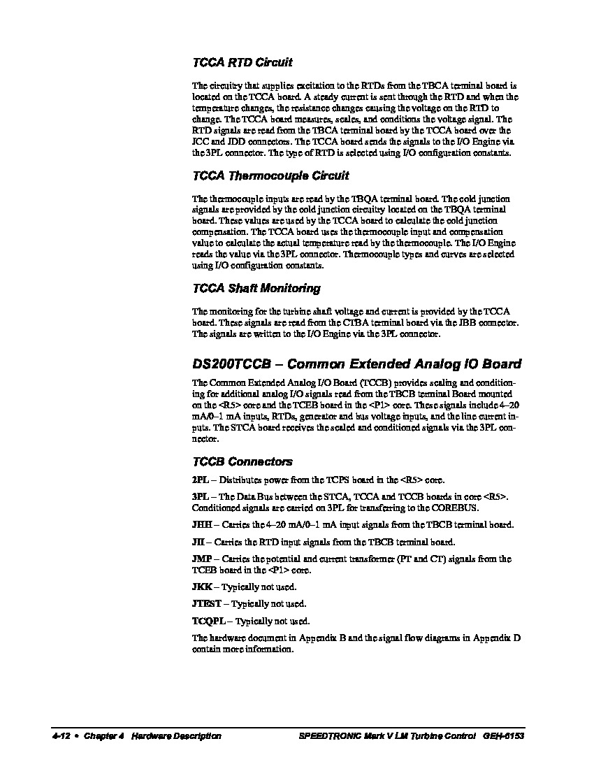
Some additional hardware specifications and component elements for this DS200TCCBG1A Common Extended Analog I/O Board are available simply upon an inspection of this product's individualized DS200TCCBG1A functional product number, which reveals informations such as this DS200TCCBG1A PCB's normal assembly type, domestic location of manufacture, TCCB functional acronym, normal PCB coating style, group one Mark V Series grouping, and lone A-rated functional revision. Luckily enough for the purposes of this DS200TCCBG1A personalized product page here, this DS200TCCBG1A device is surrounded with a something of a disproportionate amount of originally-designed original instrcutional manual materials online; likely a symptom of its Mark V Legacy Product Series attribution. With this in mind, this DS200TCCBG1A device's originally-provided connectors can be contextualized in terms of their functionalities. Each connector in this DS200TCCBG1A Common Extended Analog I/O Board's normal Mark V Series assembly will have been named through a unique amalgamation of their respective factory-printed nomenclature labels, their PIN numbers, and finally the specific style of Mark V Series signal that they were designed to transmit. This DS200TCCBG1A device's specific connectors include the:
- 2PL TCPS board Power Distribution Connector
- 3PL Data Bus between the STCA, TCCA and TCCB boards Connector
- JHH 4-20 mA/0-1 mA input signalsTBCB terminal board Connector
- JII RTD input signals from the TBCB terminal board Connector
- JMP Potential and current transformer signals from the TCEB board Connector
- JKK Connector
- JTEST Connector
- TCQPL Connector


