About the DS200TCCBG1ALD
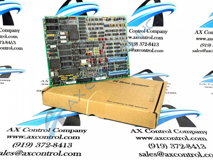
This DS200TCCBG1ALD General Electric printed circuit board was originally manufactured to exist in the Mark V Series, as described above. Also as described above, the Mark V Series from General Electric has specific applications in the management and control systems of compatible steam, wind, and gas turbine automated drive assemblies. The Mark V Series, while one of the more recent General Electric product series to feature their patented Speedtronic technology, is considered a legacy series, as its manufacture has been discontinued in the years since its original release. This TCCB-abbreviated printed circuit board product offering is more commonly referred to as an Extended Analog I/O Card; its original functional product description that appears in relevant Mark V Turbine Control System Series instructional manual documentation. While this DS200TCCBG1ALD device exists as an Extended Analog I/O Card in its own right, it is not considered the original Extended Analog I/O Card manufactured for placement in the Mark V Turbine Control System Series. The original Mark V Series product of this intended functionality is the DS200TCCBG1 parent Extended Analog I/O Card missing the DS200TCCBG1ALD product's full three-fold revision table.
Hardware Tips and Specifications
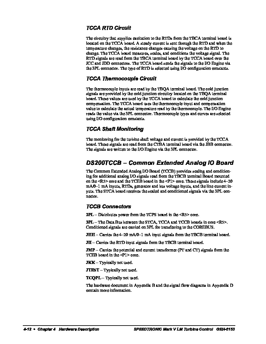
This DS200TCCBG1ALD Extended Analog I/O Card is a General Electric printed circuit board that distinguishes itself through a number of relevant hardware inclusions and specific installation procedures. The GE I/O TC2000 Analog Board DS200TCCBG1ALD features one 80196 microprocessor and multiple PROM modules in its normal style of Mark V Series assembly. It also contains one LED and 2 50-pin connectors, with the LED being visible only from the side view of the board. The IDs for this DS200TCCBG1ALD device's 50-pin connectors are JCC and JDD, and are factory-printed on this DS200TCCBG1ALD PCB's base circuit board. This DS200TCCBG1ALD PCB's various different connectors are explained in detail in its original instructional manual and datasheet attached above in the manuals tab. Some of these connectors include:
- The 2PL TCPS Board Power Distribution Connector
- The 3PL COREBUS Conditioned Signals Connector
- The JHH TBCB Board Input Signals Connector
- The JII TBCB Board RTD Input Signals Connector
- The JMP TCEB Board CT and PT Signals Connector
- The JKK Connector
- The JTEST Connector
- The TCQPL Connector
All of the mentioned connector types in the assembly of this DS200TCCBG1ALD printed circuit board have been named through a combination of their factory-printed nomenclature labels, corresponding Mark V Series products, and functional relevancy to the DS200TCCBG1ALD Extended Analog I/O Card, except for the JKK, JTEST, and TCQPL Connectors above. These connectors have not been named in this fashion as they typically go unused during normative function of this DS200TCCBG1ALD device, and should go ignored. This DS200TCCBG1ALD Extended Analog I/O Card's originally-introduced performance specifications and dimensions have no doubt been impacted through the insertion of two functional product revisions and an artwork configuration revision in this PCB's internal assembly.
The PROM modules in the assembly of this TCCB-abbreviated product offering store the configuration files for the microprocessor and other information required for the board; an insertion tool is available that you can use to remove the PROM from the socket and the tool is also used to install the PROM in the socket of the replacement board. If you want to use the same configuration file it is easy to move the PROM from the old board to the new board, if you follow the original instructions developed for this procedure by GE. First, power down the drive and disconnect it from the electrical power source. The drive receives power from an inverter and to remove the drive from power, simply remove the fuse from the inverter to disable it and shut off power to the drive. This should always be done before attempting an installation or replacement of this DS200TCCBG1ALD PCB.


