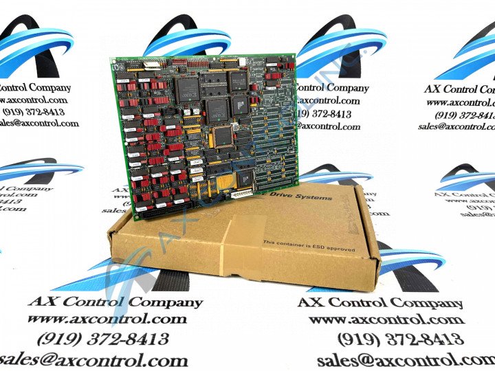
About the DS200TCCBG1BED
This DS200TCCBG1BED printed circuit board product offering was originally manufactured by General Electric, for placement in their mark V Turbine Control System Series as discussed above. The Mark V Series that this DS200TCCBG1BED PCB belongs to is characterizable as a legacy product series, due to its eventual manufacturing discontinuation that took place in the many years following its functionally-necessary manufacturing discontinuation due to obsolescence. While a now-defunct legacy product series not offered alongside a plethora of original instructional materials, the Mark V Series that this DS200TCCBG1BED printed circuit board or PCB for short belongs to is additionally definable as one of the final General Electric product series to utilize the trusted brand's Speedtronic control system technology first adopted alongside the release of the Mark I Series in the later 1960s. Before making any ultimate purchase decision on this DS200TCCBG1BED product offering, it is important to realize that it is not the original TC2000 Analog Board developed for the Mark V Series; that would be the DS200TCCBG1 parent printed circuit board missing all three of this DS200TCCBG1BED PCB's significant product revisions.
Hardware Tips and Specifications
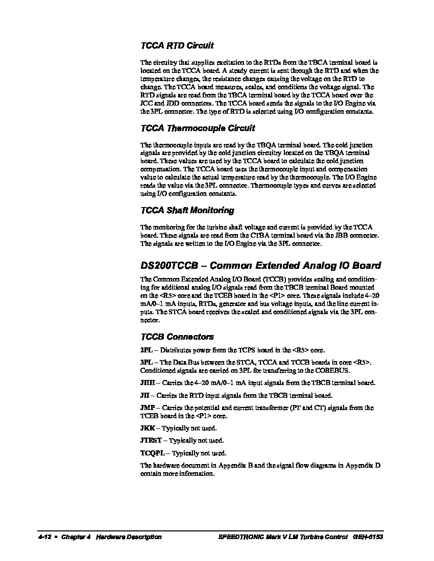
This DS200TCCBG1BED Mark V Serie's Common Extended Analog IO Board functionality is introduced through its internal assembly's acceptance of a specific series of hardware components and component specifications. The GE I/O TC2000 Analog Board DS200TCCBG1BED features one 80196 microprocessor and multiple PROM modules. It also contains one LED and 2 50-pin connectors. The LED is visible from the side view of the board. The IDs for the 50-pin connectors are JCC and JDD. The microprocessor uses the processing instructions and firmware on the PROM modules. Further programming or firmware updates are not necessary when you install the replacement board. All that is necessary is to move the PROM modules from the old board to the sockets on the replacement board. In that way, you can resume drive activity and know that processing will be the same. Five total manually-moveable hardware jumpers have been adopted into the assembly of this DS200TCCBG1BED product offering; their specific factory-printed nomenclature labels and applications are include in the DS200TCCBG1BED instructional manual attached in the manuals tab for your convenience. For example, this DS200TCCBG1BED PCB's J14-labeled jumper is utilized to establish a conenction between the RS232 serial port and the DCOM port within this DS200TCCBG1BED product's greater Mark V Turbine Control System Series' automated drive assembly. Some of the other specific connectors available in the assembly of this DS200TCCBG1BED product include:
- The 2PL TCPS Board Power Distribution Connector
- The 3PL STCA, TCCA, and TCCB Boards COREBUS Conditioned Signals Connector
- The JHH TBCB Board Input Signals Connector
- The JII TBCB Board RTD Input Signals Connector
- The JMP TCEB Board PT and CT Signals Connector
- The JKK Connector
- The JTEST Connector
- The TCQPL Connector
All of the above-listed connectors in the assembly of this DS200TCCBG1BED product offering have been named through a combination of their factory-printed nomenclature labels, their Mark V Series other product compatibilities, and their specific applications in terms of the DS200TCCBG1BED board and its greater Mark V Series automated drive assembly. The JKK, JTEST, and TCQPL Connectors in this DS200TCCBG1BED PCB's assembly have not been named as such as they exist as vestigial structures in this DS200TCCBG1BED Board's assembly not meant to be accessed during normative functionality.
You must also reconnect the ribbon cables into the same connectors on the replacement board when attempting a replacement. This applies to both the 50-pin ribbon cables and also the 34-pin ribbon cables. Because there are 5 34-pin connectors, there is a chance that you might connect the ribbon cables into the wrong connectors. There is also a chance of connecting the 50-pin connectors into the wrong connectors. All the connectors have connector IDs and even if the replacement board is a newer version, the connector IDs will be the same. You might find that the components on the replacement board are in different locations and that the components look different. Due to extensive product testing, compatibility between the versions is maintained and the replacement board will provide the same processing results as the defective board. Plug the ribbon cables into the same connectors on the new board and use the connector IDs to map the old board to the new board.


