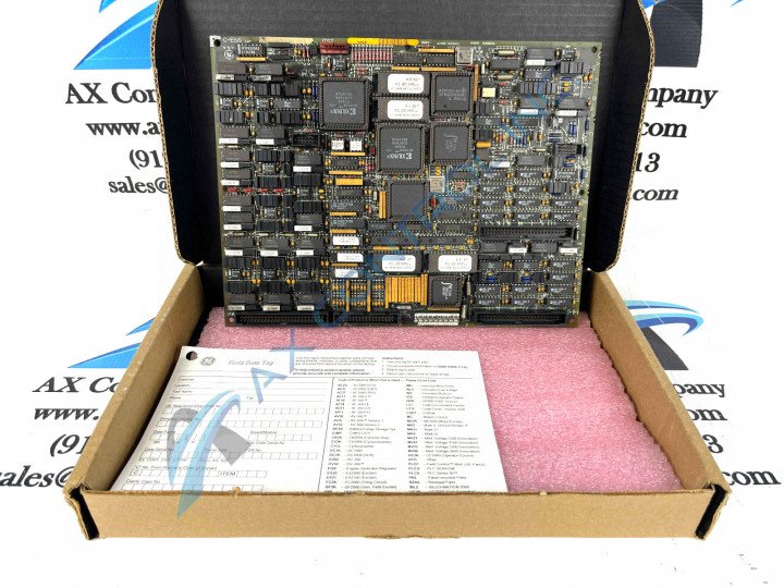
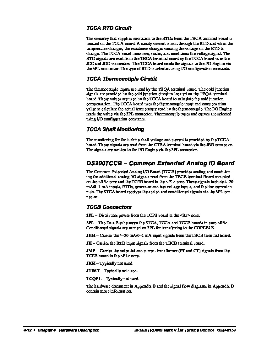
About the DS200TCCBG3BED
This DS200TCCBG3BED printed circuit board or PCB for short was originally manufactured for General Electric's Mark V Turbine Control System Series, a now-legacy series that has been discontinued for mass-production in the years following its initial release by the General Electric manufacturer. As made obvious in its name, the Mark V Series has specific applications in the control and management systems of wind, steam, and gas turbine automated drive assemblies. The Mark V Series is one of the final General Electric Mark product series to incorporate the automated industrial giant's patented Speedtronic technology into its products. This DS200TCCBG3BED PCB is more explicitly-definable as a Common Extended Analog IO Board; the official functional description it attains in its orginal General Electric and Mark V Series instructional manual materials. While definable to this extent, this DS200TCCBG3BED printed circuit board is not the original product of its specific functionality to feature within the Mark V; that would be the DS200TCCBG3 parent printed circuit board missing all three of this DS200TCCBG3BED product's significant functional revisions.
Hardware Tips and Specifications
The GE I/O TC2000 Analog Board DS200TCCBG3BED features one 80196 microprocessor and multiple PROM modules. It also contains one LED and 2 50-pin connectors. The LED is visible from the side view of the board, and has been included for basic functional fault diagnostic opportunities. The IDs for the 50-pin connectors are JCC and JDD. There are also 5 34-pin connectors on the board. There are some guidelines to follow during installation and replacement of these connectors because of the multiple ribbon cables potentially connected to the DS200TCCBG3BED board. The best practice is to route signal cables far from power cables and to minimize the length of the run that the two cables are in parallel. If the power cables and the signal cables cross at 90 degree angle the interference is minimized. If the board contains fibre optic cables you should know that they are not subject to interference and can be near power cables. The ribbon cable if not properly routed can block the air flow over the critical heat generating components. For these reasons examine the cable routing and use the same routing when you install the replacement DS200TCCBG3BED board. Fortunately for our sakes, the various connectors afforded to the assembly of this DS200TCCBG3BED PCB are described in detail in this device's original product manual. Some of these connectors include:
- The 2PL TCPS Power Distribution Connector
- The 3PL COREBUS Conditioned Signals Connector
- The JHH TBCB Board Input Signals Connector
- The JII TBCB Board RTD Input Signals Connector
- The JMP TCEB Board Potential and Current Signals Connector
- The JKK Connector
- The JTEST Connector
- The TCQPL Connector
All of these listed connectors have been named through a combination of their individual factory-printed nomenclature labels, corresponding Mark V Series interfacing potentials, and their function as applicable to the DS200TCCBG3BED printed circuit board and its greater Mark V Turbine Control System Series automated drive assembly. All of the connections made to the base circuit board of this DS200TCCBG3BED product should be somewhat-protected by the normal style of printed circuit board coating that has been chemically applied to it, which exists as a thick rudimentary layer of base circuit board daily wear and tear protection that adheres and protects individual hardware component elements in its assembly on a functional priority basis. Before making a final purchase decision on this DS200TCCBG3BED board, it is important to understand that this product's originally-produced performance specifications and dimensions have no doubt been altered through its full three-fold revision table.


