About the DS200TCCBG8BED
This DS200TCCBG8BED printed circuit board product offering plays a crucial role as a Common Extended Analog IO Board in its greater Mark V Series. The Mark V Series designed by General Electric is a series of control and management systems developed for specific use in the automated drive assemblies of compatible, wind, steam, and gas turbines. The Mark V Series, while one of the more recently-developed General Electric product series featuring their patented Speedtronic technology, is considered a legacy series, as its manufacture has been discontinued by General Electric in the years since its first conception. This DS200TCCBG8BED Common Extended Analog IO Board may be referred to as its secondary applicable functional product description as a TC2000 Analog Board, which suggests an additional allegiance to the Mark V Series TC2000 subseries. This DS200TCCBG8BED printed circuit board is not the original Common Extended Analog IO Board developed for the Mark V; that would be the DS200TCCBG8 parent printed circuit board missing all three of this DS200TCCBG8BED product offering's three significant product revisions.
Hardware Tips and Specifications
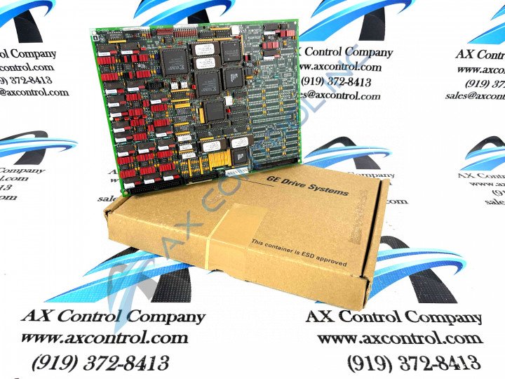
Similarly to any Mark V Turbine Control System Series component product, this DS200TCCBG8BED PCB makes use of a standard number of functionality-introducing hardware component inclusions and specifications. The GE I/O TC2000 Analog Board DS200TCCBG8BED features one 80196 microprocessor and multiple PROM modules. It also contains one LED and 2 50-pin connectors. The LED is visible from the side view of the board, and has been included for functional fault monitoring purposes. The IDs for the 50-pin connectors are JCC and JDD; this DS200TCCBG8BED PCB's microprocessor is a 16-bit microprocessor and is used to manage the operations of the board. Several different styles of Mark V Series connectors are made available in the assembly of this DS200TCCBG8BED Common Extended Analog IO Board for the maximization of interfacing opportunities. Some of these various connectors include:
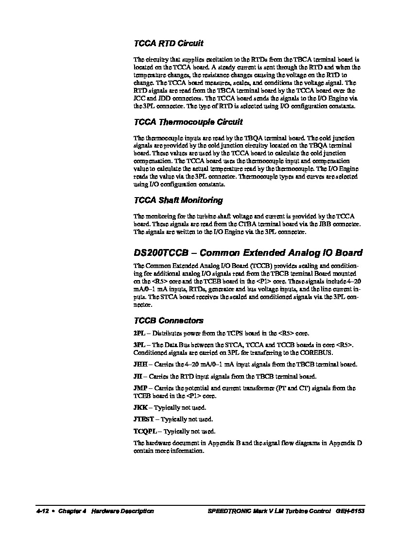
- The 2PL TCPS Board Power Distribution Connector
- The 3PL COREBUS Data Bus Conditioned Signal Connector
- The JHH TBCB Board Input Signals Connector
- The JII TBCB Board RTD Input Signals Connector
- The JMP TCEB Board PT and CT Signals Connector
- The JKK Connector
- The JTEST Connector
- The TCQPL Connector
As you have probably noticed, all of the above listed connectors in the assembly of this DS200TCCBG8BED printed circuit board have been named through a combination of their factory-printed nomenclature labels and their functionality to the DS200TCCBG8BED Common Extended Analog IO Board and greater Mark V Series automated drive assembly, except for the JKK, JTEST, and TCQPL connectors. These three connectors have not been named in-depth as they typically go unused during normative function of the DS200TCCBG8BED Common Extended Analog IO Board, and should be largely ignored.
The PROM modules are installed in sockets on the DS200TCCBG8BED board which enable the servicer to remove the modules or install them with use of a hand tool. The PROM modules contain firmware and programming instructions that control the microprocessor. The modules are erasable which means that updates can be applied to them. The updates can be downloaded from a web site and applied to the module. The replacement DS200TCCBG8BED module comes without PROM modules installed; this allows the installer to easily move the PROM modules from the old board to the replacement. In that way, the firmware is the same which ensures that the microprocessor will behave the same when the drive is restarted. Proper guidelines for ESD must be followed due to the fact that the PROM modules are damaged by static. That is, the memory can be corrupted or erased by static. To prevent that, wear a wrist strap at all times when you install the replacement board. One end of the wrist strap is attached to the arm or wrist of the installer, with the other end being clipped to a metal surface that is clear of paint or other coverings.


