About the DS200TCDAG1ADA
This DS200TCDAG1ADA Digital I/O Board was, as mentioned just above, originally a product offering manufactured for General Electric's Mark V Series. The Mark V Series from GE is the fifth generation of Speedtronic-fueled turbine control systems manufactured by the industrial giant retailer General Electric, who started the mark series in the early to late 1960s using similar Speedtronic technology. This DS200TCDAG1ADA Digital Input/Output Board or Digital IO Board for short is not actually the original version of the Mark V Series Digital IO Board, however, as it modified the original DS200TCDAG1 parent circuit board through its inclusion of three significant product revisions.
Hardware Tips and Specifications
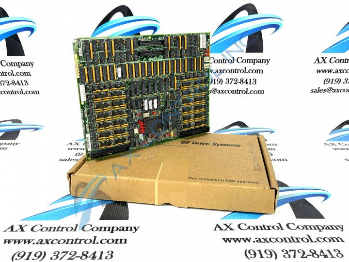
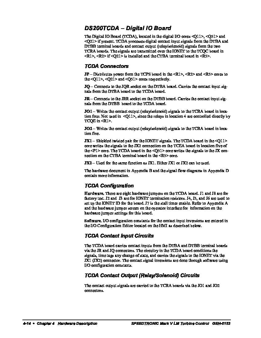
Much like any other Mark V Series product offered for repair or replacement here at AX Control, this DS200TCDAG1ADA Digital IO Board has its own series of individualized hardware traits and specifications that contribute towards its intended functionality. For starters, the General Electric Digital I/O Board model DS200TCDAG1ADA features only one microprocessor and multiple programmable read-only memory (PROM) modules. It also contains an integrated block of 10 LED lights and a pair of 50-pin connectors. This GE Digital I/O Board DS200TCDAG1ADA also is populated with up to 8 jumpers and 1 LED that is visible from the side of the board. One of this DS200TCDAG1ADA PCB's two connectors is a 50-pin connector identified as JQ and the other 50-pin connector is identified as JR. The IDs for each individual hardware component are printed on the surface of the board.
When you plan to replace the GE Digital I/O Board DS200TCDAG1ADA because it is defective, the replacement board might be a newer version of the same model. And in the interest of product improvement, the latest version will include the latest design changes. This might require that components need to be rearranged on the board in order to accommodate new circuit designs. Even if the 50-pin connectors are located in new positions, one 50-pin connector will be assigned JQ as the ID and the other will be assigned JR as their respective ID. The ribbon cables can be connected to the appropriate connectors based on these printed identifiers. The jumpers adopted into the assembly of this DS200TCDAG1ADA Digital IO Board enable a signal to be made between 2 of the 3 pins associated with the jumper. For example, the jumper can cover pins 1 and 2 or pins 2 and 3. If pins 1 and 2 are covered the signal passes between pins 1 and 2 and pin 3 is not connected to the circuit.


