About the DS200TCDAG1B
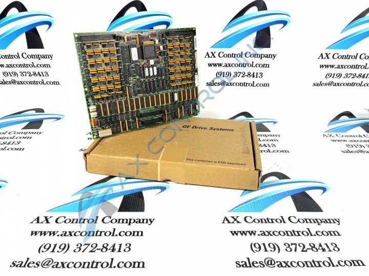
This DS200TCDAG1B printed circuit board product offering from General Electric is a generally well-supported PCB option that exists as a member of the Mark V Series of Turbine Control Systems, as mentioned above. The Mark V Series from trusted automated industrial retailer General Electric is an obsolete legacy product series, as its manufacture has been discontinued by General Electric in the years since its initial release. With this being true, the DS200TCDAG1B PCB featured on this personalized product page's Mark V Series is one of the later product series developed to include General Electric's patented Speedtronic style of technology. This specific DS200TCDAG1B PCB is better-definable through its official functional product description as a Digital IO Board or Digital Input/Output Board, the official functional description that it is referred to by in original Mark V Series instructional manual materials. While this DS200TCDAG1B PCB is certainly a Digital IO Board in its own right, it is not considered the original product offering with its intended functionality to exist within the Mark V product series; that would be the DS200TCDAG1 parent Digital IO Board missing this DS200TCDAG1B PCB's singular B-rated functional product revision.
Hardware Tips and Specifications
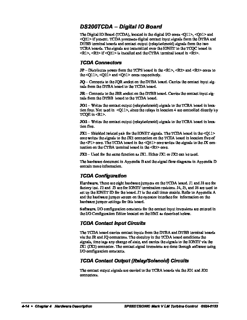
As with any product offering included with the Mark V Turbine Control System Series, this DS200TCDAG1B PCB is unique in a number of necessary hardware components and specifications to gain its intended Mark V automated drive assembly application and functionality. The GE Digital I/O Board DS200TCDAG1B features one microprocessor and multiple programmable read-only memory (PROM) modules. It also contains 1 block of 10 LEDs and 2 50-pin connectors. This GE Digital I/O Board DS200TCDAG1B also is populated with 8 jumpers and 1 LED that is visible from the side of the board. The 50-pin connectors in this product's assembly carry signals that are received by the board from other components in the drive. Some of the signals carried by the 50-pin connectors are transmitted by other boards and components to the GE Digital I/O Board DS200TCDAG1B. The various connector type made available to the DS200TCDAG1B PCB are defined as the JP, JQ, JR, JO1, JO2, JX1, and JX2 connectors; with each individual connector function being explained in great detail in the original Mark V Series instructional manual attached above. It should be noted that the JX1 and JX2 connectors, as defined by General Electric, have the exact same function, and can be used interchangeably. Before making a final purchase decision on this DS200TCDAG1B Mark V Turbine Control System Series product, it is important to note that this PCB's original performance specifications and dimensions have been altered from their original statuses through the use of a B-rated functional product revision.
The 50-pin connectors in the assembly of this DS200TCDAG1B PCB are connected to ribbon cables that are comprised of 50 individual strands of wire and each strand is insulated from the other strands to provide a separate signal. Each strand is made of several wires which are easily broken or disconnected from the connector at the end of the ribbon cable. If a connection to the ribbon cable is broken the signal is lost to the DS200TCDAG1B PCB also. It might require running the diagnostic tools to find the missing signal. So to avoid any missing signals, follow some guidelines when you handle the ribbon cables. Pulling on the ribbon cable to remove it from the board can break the wire connections inside it. Instead, use the plastic connector to disconnect it from the 50-pin connector on the board; firmly hold the connector and pull it straight out of the connector, before moving the ribbon cable out of the way without disturbing the cable routing of the ribbon cable in the interior of the drive.


