About the DS200TCDAG2B
As explained before, This DS200TCDAG2B printed circuit board product offering was originally manufactured by General Electric, specifically for placement in their Mark V Turbine Control System Series. The Mark V Series that this DS200TCDAG2B PCB belongs to, as evidenced by its full extended series name, has specific applications in the management and control systems of compatible and popular wind, steam, or gas turbine control and management systems, and is considered to exist as a now-obsolete General Electric legacy product series, as its manufacturing discontinuation was deemed necessary due to obsolescence in the many years past its initial release. This DS200TCDAG2B printed circuit board or PCB for short's greater Mark V Series may be generally poorly-updated as it is a legacy product series, although it is at least up to date in terms of its control system technology, as it is one of the final General Electric Mark product series to utilize the patented Speedtronic control system technology first introduced in the Mark I Series in the later 1960s. This DS200TCDAG2B PCB is officially defined in internet-available General Electric Mark V Series instructional manual materials as a Digital I/O Board, although the originally-developed Mark V Series product offering of this specific functionality is the DS200TCDAG2 parent Digital I/O Board missing this DS200TCDAG2B PCB's B-rated functional product revision.
Hardware Tips and Specifications
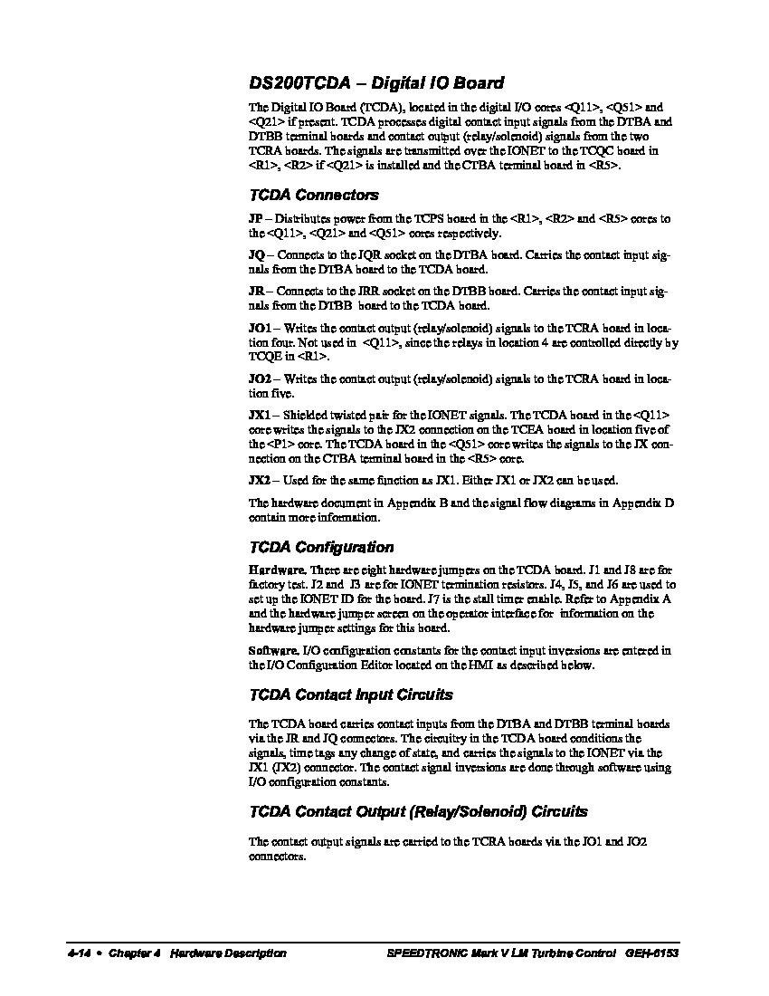
This DS200TCDAG2B PCB's Digital I/O Board functionality is introduced with its internal assembly's acceptance of a specific series of hardware components; primarily connectors of different styles given this DS200TCDAG2B Board's Input/Output function.The GE Digital I/O Board DS200TCDAG2B features one microprocessor and multiple programmable read only memory (PROM) modules. It also contains 1 block of 10 LEDs and 2 50-pin connectors. The GE Digital I/O Board DS200TCDAG2B also is populated with 8 jumpers and 1 LED that is visible from the side of the board. The 50-pin connectors on the GE Digital I/O Board DS200TCDAG2B transmit signals to the DS200DTBA and the DS200DTBB boards installed in the drive. The 50-pin connectors attach to ribbon cables that are plugged into the DS200TCDAG2B on one end. The other end of the ribbon cable attaches to either the DS200DTBA or the DS200DTBB boards. Before you remove the board to replace it note how the 50-pin ribbon cables are routed in the interior of the drive and maintain that routing when you install the replacement board. Luckily enough for the purposes of this DS200TCDAG2B Digital I/O Board's personalized product page here, each of the Mark V Series connectors available in its assembly have been listed online in General Electric instructional manual materials, and embedded in the DS200TCDAG2B instructional manual attached above in our manuals tab for your convenience. Some of this DS200TCDAG2B PCB's connectors include:
- The JP TCPS Board Power Distribution Connector
- The JQ DTBA and TCDA Boards Contact Input Signals Connector
- The JR DTBB and TCDA Boards Contact Input Signals Connector
- The JO1 TCRA Board Contact Output Signals Connector
- The JO2 TCRA Board Contact Output Signals Connector
- The JX1 and JX2 TCDA, TCEA, and CTVA Boards IONET Signals Daisy-chained Connectors
All of the above-listed connectors in the normal Mark V Series assembly of this DS200TCDAG2B product offering have been named through a combination of their particular factory-printed nomenclature labels, their Mark V Series compatible products and interfacing opportunities, and finally the specific type of signals they have been designed to transmit. This DS200TCDAG2B PCB's JO1 and JO2 jumpers are different as they pertain to different specific locations within the DS200TCDAG2B board's greater Mark V Series, as again revealed in the DS200TCDAG2B instructional manual attached above. The DS200TCDAG2B is populated with a block of 10 LEDs that are organized in one row. When the board is receiving power and is processing normally, the LEDs flash in a sequence from left to right. It will continue the sequence as long as normal processing continues. If an error or warning is encountered, the LEDs flash in a pattern to represent the error or warning code. When the board is powered on all 10 LEDs are lit simultaneously to test the functionality of the LEDs. When the board is installed in the drive between several other boards in the board cabinet, the block of 10 LEDs is not visible. However, the operator can view the 1 green LED that is located on the side of the board and is designed to give a quick visual indication of the state of the board.


