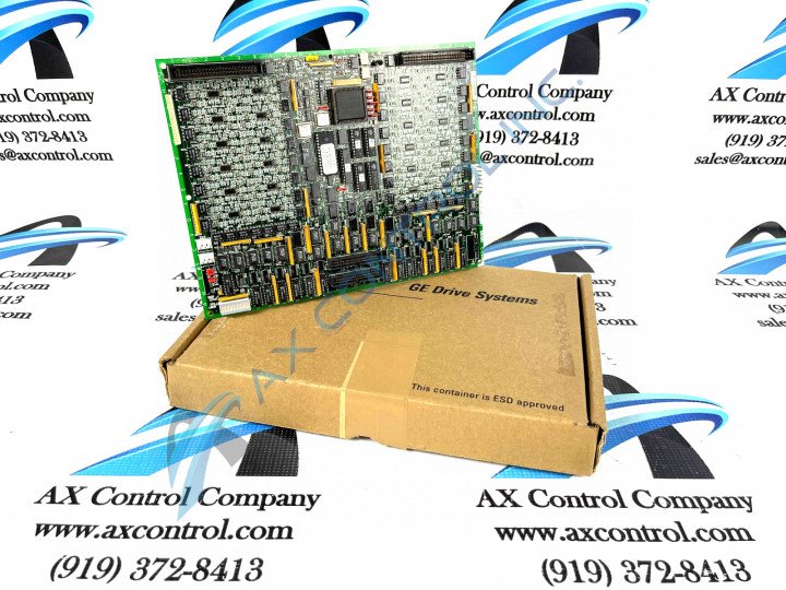
About the DS200TCDAH1BHD
This DS200TCDAH1BHD printed circuit board was originally designed for placement in the Mark V Turbine Control System Series, as described above. The Mark V Series that this DS200TCDAH1BHD product offering belongs to is classifiable as a legacy General Electric product series, due to its necessary manufacturing discontinuation that took place in the years following its original production due to obsolescence. This DS200TCDAH1BHD printed circuit board or PCB for short's Mark V Turbine Control System Series, while a now-obsolete legacy product series, has additionally been cited as one of the final General Electric product series to incorporate the patented Speedtronic control system technology into its various offerings. The Speedtronic control system technology seen in this DS200TCDAH1BHD PCB and many other mark V Series products was first introduced to the automated industrial landscape through the release of the Mark I Series in the late 1960s. This DS200TCDAH1BHD printed circuit board was specifically developed for the Mark V Series functional role of a Digital IO Board or Digital Input/Output Board, although the original product of this Mark V Series functional role is the DS200TCDAH1 parent printed circuit board missing all three of this DS200TCDAH1BHD device's significant product revisions.
Hardware Tips and Specifications
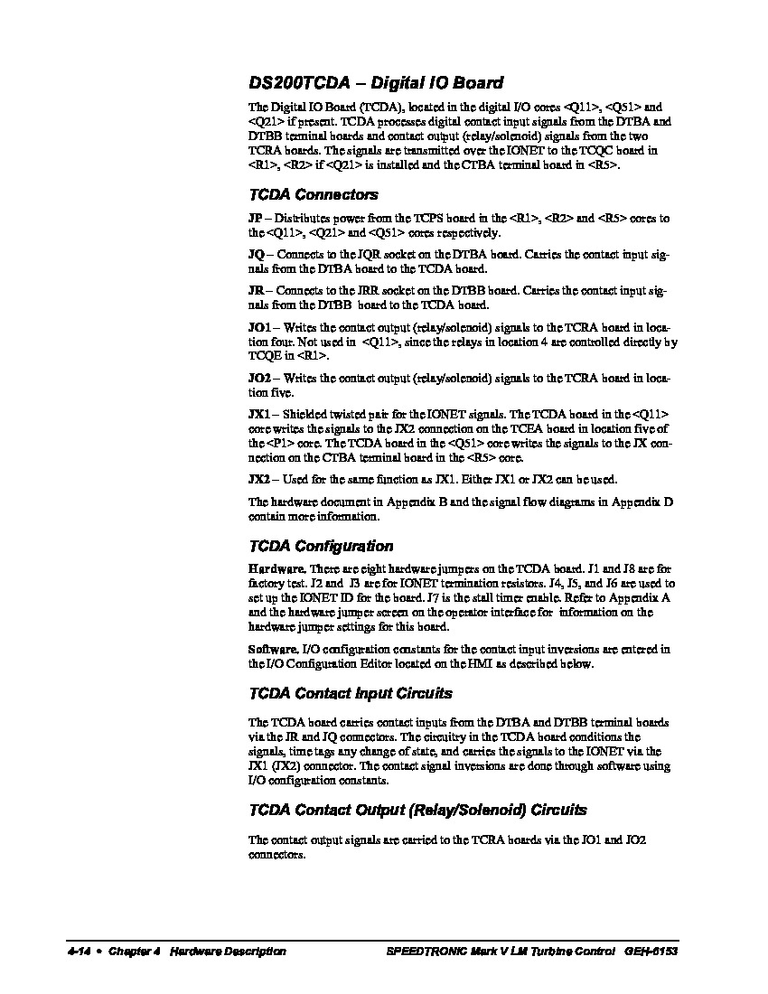
As with any General Electric printed circuit board product offering, Mark V Series or not, this DS200TCDAH1BHD PCB utilizes a standard number of functionality-introducing hardware components and component specifications. The GE Digital I/O Board DS200TCDAH1BJE features 8 jumpers, one LED on the side of the board, and 2 3-pin connectors. It also contains 1 block of 10 LEDs and 2 50-pin connectors. Each jumper on the GE Digital I/O Board DS200TCDAH1BJE has a ID. The prefix for each jumper ID is JP followed by a numerical value. For example, the ID for one jumper is JP1. The ID for another jumper is JP8. Before you replace the board, identify each jumper and document which jumpers are covered. Then, examine the new board and set the jumpers on the replacement board to match the old board. For example, if JP1 has pins 1 and 2 covered on the old board, make sure that the replacement board has jumpers 1 and 2 covered also. The various connectors made available to the assembly of this DS200TCDAH1BHD product have been identified in the DS200TCDAH1BHD instructional manual above, for your convenience. This is true of most of the specialized hardware components in the assembly of this DS200TCDAH1BHD PCB, including its fuses and various pieces of customizable hardware. Some of the connectors in this DS200TCDAH1BHD PCB's assembly include:
- The JP TCPS Board Power Distribution Connector
- The JQ DTBA Board Contact Input Signals Connector
- The JR DTBB Board Contact Input Signals Connector
- The JO1 TCRA Board Contact Output Signals Connector
- The JO2 TCRA Board Contact Output Signals Connector
- The JX1 and JX2 IONET Signals Daisy-Chained Connectors
All of these above listed DS200TCDAH1BHD Board connectors have been named through a combination of their factory-printed nomenclature lables, their Mark V Series interfacing potentials and compatible products, and finally their specific intended application in terms of the DS200TCDAH1BHD board and its greater Mark V Turbine Control System Series. The jumpers are used to configure the DS200TCDAH1BHD board to meet the specific requirements of the site. Before the board is installed for the first time, the installer can refer to the information that shipped with the board to learn how the jumper positions define the operation of the board. The installer can change the positions of the jumpers to best suit the needs of the site. When the board ships from the factory the jumpers are in the default positions. This is the standard setting that typically meets the needs of the site. Some of the jumpers are not for customer use and must stay in the position in which they shipped from the factory.


