About the DS200TCDAH1BJE
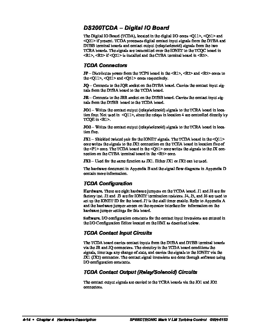
This DS200TCDAH1BJE product offering is a printed circuit board manufactured for use in General Electric's Mark V Turbine Control System Series, as mentioned before. The Mark V Series that this DS200TCDAH1BJE product belongs to has specific applications in the control and management systems of compatible wind, steam, and gas turbine automated drive assemblies, and is considered a General Electric legacy series due to its eventual manufacturing discontinuation in the years past its initial series release. This DS200TCDAH1BJE printed circuit board or PCB for short's greater Mark V Series, while a legacy series, is also one of the final General Electric product series to make use of the patented Speedtronic control system technology first introduced with the rollout of the Mark I Series in the late 1960s. While this DS200TCDAH1BJE PCB is better-definable through its manual-included functional product description as a Digital I/O Board, the original product of this functionality to make an appearance in the Mark V Series is the DS200TCDAH1 parent printed circuit board missing all three of this DS200TCDAH1BJE PCB's three significant revisions.
Hardware Tips and Specifications
As with any Mark V Series product offering available in our new and reconditioned General Electric inventory; this DS200TCDAH1BJE PCB makes use of its own series of hardware components introducing its intended series functionality. The GE Digital I/O Board DS200TCDAH1BJE features 8 jumpers, one LED on the side of the board, and 2 3-pin connectors. It also contains 1 block of 10 LEDs and 2 50-pin connectors. This Digital I/O board is part of General Electric's Mark V Speedtronic turbine control system. The ID of the LED on the side of the board is CR9. It is green in color when lit and it gives an indication that the board is receiving power. When the LED flashes it indicates that processing is occurring on the board. When the LED is not lit, it shows that the board is not receiving power or is not responding to voltage. The LED is visible when the board is installed between other boards in the rack cabinet. You can view the LED from the window in the rack cabinet. Several different styles of Mark V Turbine Control System Series connectors are available to the assembly of this DS200TCDAH1BJE PCB. Some of these different connectors include:
- The JP TCPS Board Power Distribution Connector
- The JQ DTBA Board JQR Socket Connector
- The JR DTBB Board JRR Socket Connector
- The JO1 TCRA Board Contact Output Signals Connector
- The JO2 TCRA Board Contact Output Signals Connector
- The JX1 and JX2 TCDA Board Daisy-Chained IONET SIgnals Connectors
All of the connectors listed above in the assembly of this DS200TCDAH1BJE PCB have been named through a combination of their factory-printed nomenclature labels, Mark V Series interfacing potentials, and specific functionality in terms of the DS200TCDAH1BJE printed circuit board and its greater Mark V Turbine Control System Series automated drive assembly. The JO1 and JO2-labeled connectors in this DS200TCDAH1BJE PCB's assembly are different as they correspond to different locations in the Mark V Series automated drive assembly, as revealed in the DS200TCDAH1BJE instructional manual embedded above. If the LED in this DS200TCDAH1BJE PCB's assembly is not lit, use the diagnostic tools to obtain a list of errors and warnings that have been recorded. The diagnostics tools also provide information on the health and condition of the boards in the drive. An individual familiar with the drive can determine from the diagnostics the cause of the problems and also how to resolve the issues. GE manuals and other documentation will provide additional details. The DS200TCDAH1BJE connects to the DS200DTBA and the DS200DTBB boards through the 50-pin connectors on the board. The IDs of the 50-pin connectors are JQ and JR. 50-pin ribbon cables are routed through the interior of the drive and provide the connection between the boards. Cable routing is important because it limits the interference to which the signal is subjected from other cables in the drive.


