About the DS200TCEAG1A
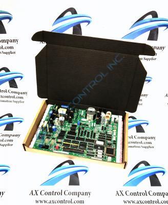
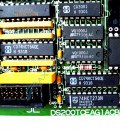
The DS200TCEAG1A is an Emergency Overspeed Board produced by General Electric Multilin for the Mark V series. The Mark V Series that this DS200TCEAG1A product belongs to is considered a General Electric legacy series, as it has been discontinued for manufacture in the years since its initial release. While a legacy series, the Mark V Series that this DS200TCEAG1A PCB belongs to is one of the final General Electric product series to make use of their patented Speedtronic control system technology, and has specific applications in the management and control systems of compatible wind, steam, and gas turbine assemblies. This DS200TCEAG1A printed circuit board product offering is better-definable by its official functional product description as a DS200TCEAG1A Emergency Overspeed Board, as revealed in pertinent Mark V Turbine Control System Series instructional manual materials.
Hardware Tips and Specifications
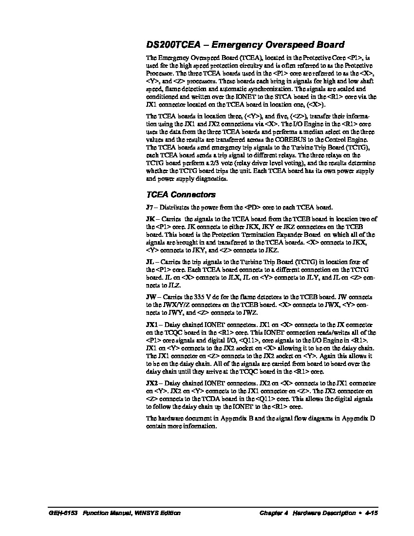
Also called a Protective Processor, the board primarily works to safeguard the Mark V by making efficient use of the high speed protection circuitry. The Emergency Overspeed Board is also capable of bringing in signals for automatic synchronization, flame detection, low shaft speed, and high shaft speed. The aforementioned signals are scaled and conditioned, and then written to the STCA board over the IONET. TCEA boards can also send emergency trip signals to the TCTG (Turbine Trip Board); if enough relays "vote" to trip the unit, the TCTG board can handle this process. The internal assembly of this DS200TCEAG1A product offering additionally makes use of its own series of connectors, as outlined in the original DS200TCEAG1A instructional manual material attached in the manuals tab above. These various connectors include:
- The J7 TCEA Board Power Connector
- The JK TCEB Board Signals Connector
- The JL TCTG Board Trip Signals Connector
- The JW TCEB Board Flame Detection Signals Connector
- The JX1 and JX2 Daisy Chained IONET Signal Connectors
All of these listed connectors in the assembly of this DS200TCEAG1A Emergency Overspeed Board have been named through a combination of their respective factory-printed nomenclature labels, Mark V Series interfacing potentials, and specific application for the DS200TCEAG1A Emergency Overspeed Board and its greater Mark V Series automated drive assembly. Each DS200TCEAG1A Board comes equipped with its own internal power supply and power supply diagnostics.
The hardware configuration is straightforward when referencing the GEH-6153 user manual. Jumpers J31 and J1 located on the TCEA board are both used for testing purposes. The TCEA's jumpers J4-J6 establish IONET addresses for the board. Jumpers J2-J3 provide for IONET termination resistors. J12-J21 jumpers help assign overspeed trip frequency settings, specifically for the high pressure shaft. Meanwhile, jumpers J8-J11 and J22-J27 provide the same functions for the low pressure shaft. The hardware jumper screen and Appendix A both contain more information on hardware jumper settings. The user manual also has detailed information on the various other jumpers located on the board.


