About the DS200TCEAG1B
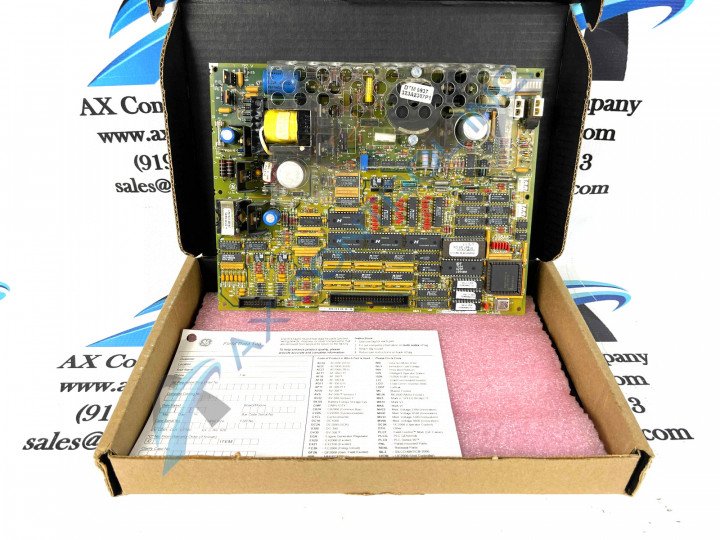
This DS200TCEAG1B printed circuit board or PCB for short was originally developed to exist as an Emergency Overspeed Board within the greater Mark V Turbine Control System Series. The Mark V Series is one of the more recent additions to the slew of Mark-named product series offered with General Electric Speedtronic technology, and specifically applies to wind, steam, or gas turbine control systems and automated drive assemblies. This DS200TCEAG1B printed circuit board is not the original Emergency Overspeed Board that was manufactured by General Electric for placement in their Mark V Turbine Control System Series; that would be the similarly-named DS200TCEAG1 printed circuit board notably missing this DS200TCEAG1B product offering's singular B-rated functional product revision.
Hardware Tips and Specifications
This DS200TCEAG1B Emergency Overspeed Board has its own particular set of hardware component inclusions and specifications, as revealed in original Mark V Series instructional manual documentation. The General Electric Emergency Overspeed Board model DS200TCEAG1B features one microprocessor and multiple programmable read only memory (PROM) modules. It also contains 3 fuses, 30 jumpers, and a pair of bayonet connectors. The DS200TCEAG1B board monitors the Mark V Series drive for over speed and flame detection trip conditions and shuts down the drive as appropriate. The bayonet connectors in the assembly of this DS200TCEAG1B Emergency Overspeed Board are used to connect the board to other devices and boards in the drive; these male bayonet connectors on the end of the cables require some consideration before you connect them to the female connectors on the board, as detailed in depth in GE instructional manual materials. To remove a bayonet connector, hold the connector with one hand and with the other hand secure the board to keep it from bending or moving. Pull the bayonet connector out of the female connector on the board and put the cable aside until you are ready to connect it to the replacement board.
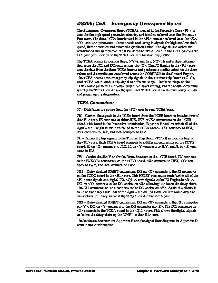
Several specific connectors and integrated circuits are incorporated into the assembly of this TCEA-abbreviated PCB. This DS200TCEAG1B Mark V Series printed circuit board's circuits are tasked with various diagnostic functions relating to this DS200TCEAG1B PCB's greater overspeed processing functionality. Some of these integrated circuits include the TCEA Flame Detection Circuits, the TCEA Turbine Overspeed Circuit, and the TCEA Automatic Synchronizing Circuit. Each of these circuits has been named in terms of their functionality to the greater DS200TCEAG1B printed circuit board and Mark V Series automated drive assembly. The various connectors made available to owners of the DS200TCEAG1B Emergency Overspeed Board comprise of:
- The J7 PD Core Power Distribution Connector
- The JK TCEB Board Signal Connector
- The JL TCTG Board Trip Signal Connector
- The JW TCEB Board Flame Detection Signal Connector
- The JX1 and JX2 Daisy Chained IONET Connectors
Similarly to the integrated circuits discussed above, all of these connectors available in the assembly of this DS200TCEAG1B printed circuit board have been described in terms of their factory-printed nomenclatures and intended applications. All of the hardware in the assembly of this TCEA-abbreviated Emergency Overspeed Board should receive at least some basis of protection from the thick protective layer offered by this DS200TCEAG1B PCB's normal style of PCB protective coating. While this DS200TCEAG1B device's various hardware offerings are generally well-protected, so too are this DS200TCEAG1B device's different software configuration options, as this DS200TCEAG1B device's software configuration is chiefly handled by this DS200TCEAG1B product's usage of the IO Configuration Editor made standard to the Mark V Turbine Control System Series that this DS200TCEAG1B product is considered a component member of.


