About the DS200TCEAG1BTF
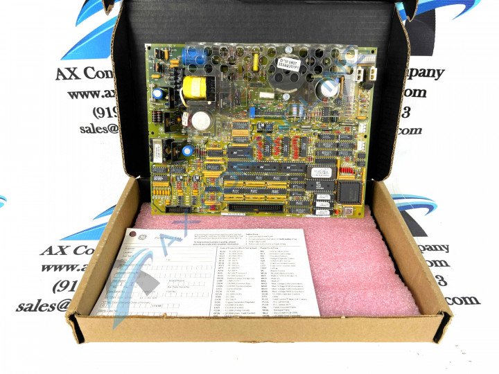
This DS200TCEAG1BTF General Electric printed circuit board is classified functionally as an Emergency Overspeed Board, as explained above and reinforced in original General Electric instructional manual materials. This model of DS200TCEAG1BTF Emergency Overspeed Board is actually not the originally-intended product with its intended functionality that was developed for the Mark V Series of turbine control systems; that would be the DS200TCEAG1 parent printed circuit board missing this DS200TCEAG1BTF product's three total significant revisions. As a Mark V Series member, this DS200TCEAG1BTF PCB incorporates many of the streamlined elements of its greater series into its assembly, beginning with the Speedtronic technology introduced with GE's primary Mark I Series. While the Mark V Series that this DS200TCEAG1BTF product belongs to is still able to attract some niche demand on the greater automated industrial marketplace, it has to be considered obsolete as a whole as it is was discontinued for manufacture in one of the years past its initial release due to a manufacturer-identified functional series obsolescence.
Hardware Tips and Specifications
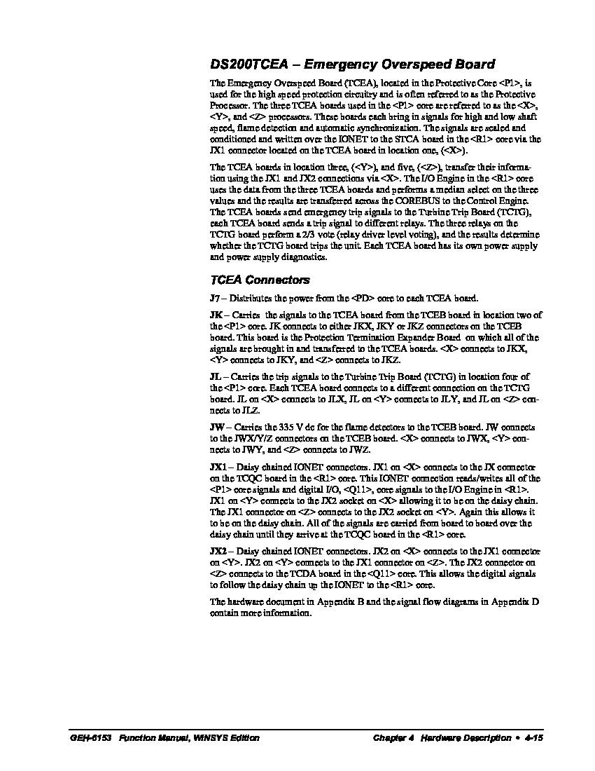
As with any General Electric Mark V Series printed circuit board, this DS200TCEAG1BTF PCB makes use of its own necessary set of hardware components and specific hardware component specifications. The GE Emergency Overspeed Board DS200TCEAG1BTF features one microprocessor and sockets for multiple programmable erasable read only memory (EPROM) modules. It also contains 3 fuses, 30 jumpers, and 2 bayonet connectors. The fuses on the GE Emergency Overspeed Board DS200TCEAG1BTF are used to protect the components on the board from voltage spikes or other irregular voltage conditions; each fuse protects a component or multiple components on the board, and is accompanied by a factory-printed ID on the board. Each fuse is prefixed with FU and suffixed with a number, for example; one fuse is FU1, one is FU2, and one other is FU3. When you replace a fuse you must make sure to replace it with a fuse of the same type and rating. A fuse that allows more current might cause damage to the board components on this DS200TCEAG1BTF PCB. For that reason inserting a fuse with the same specification is important. Moving past the various fuses incorporated into the assembly of this DS200TCEAG1BTF PCB, a secondary highlight-able hardware component to this Mark V Series product is its varied and unique number of connectors, which present different interfacing opportunities. Some of the connectors included in this DS200TCEAG1BTF PCB's assembly are:
- The J7 PD Core TCEA Board Power Connector
- The JK TCEB Board P1 Core Signal Connector
- The JL TCTG Board Trip Signals Connector
- The JW TCEB Board Flame Detection Signal Connector
- The JX1 and JX2 Daisy Chained IONET TCQC Board Connectors
Each of the previous connectors mentioned above is defined in terms of its functionality to the greater DS200TCEAG1BTF Emergency Overspeed Board and greater Mark V Turbine Control System automated drive assembly. In a surprising turn for a Mark V Series printed circuit board, no connector included in this DS200TCEAG1BTF PCB's assembly goes unused normally as a vestigial structure. This DS200TCEAG1BTF Emergency Overspeed Board additionally incorporates several manually-movable hardware jumpers into its assembly for customization purposes; their placements and applications are provided in the instructional manual available in the manuals tab above. As once again detailed in the various instructional manual materials above, this DS200TCEAG1BTF device's central functionality is introduced through a series of specialized circuits made available to its base printed circuit board. Some of these circuits can be named as the TCEA Flame Detection, TCEA Turbine Overspeed, and finally the TCEA Automatic Synchronizing Circuits. Each one of these circuits is detailed in depth in the instructional materials attached above.


