About the DS200TCEBG1
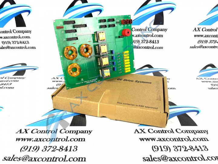
As alluded to before, this DS200TCEBG1 printed circuit board product offering was originally designed and manufactured by General Electric, specifically for placement in their Mark V Turbine Control System Series. As you may have been able to guess based on its full extended series name, the Mark V Series that this DS200TCEBG1 printed circuit board belongs to has specific applications in the management and control systems of popular and compatible wind, steam, and gas turbine control and management systems. This DS200TCEBG1 product offering's greater Mark V Turbine Control System Series is additionally defined as a now-obsolete legacy product series, as its manufacture has been discontinued in the many years since its initial release. This DS200TCEBG1 printed circuit board or PCB for short's Mark V Series, while a now-obsolete legacy General Electric product series, is at least well-updated in one respect, as it is one of the final-developed General Electric product series to make use of their patented Speedtronic control system technology. The Speedtronic control system technology seen in many of this DS200TCEBG1 PCB's Mark V Series' product offerings was first released with the conception of the Mark I Series in the late 1960s. This DS200TCEBG1 PCB exists as a Protective Termination Expander Board, and is the base-revised and unedited version of its specific functional product, as evidenced by its DS200TCEBG1 functional product number's lack of any trailing, revision-indicating digits.
Hardware Tips and Specifications
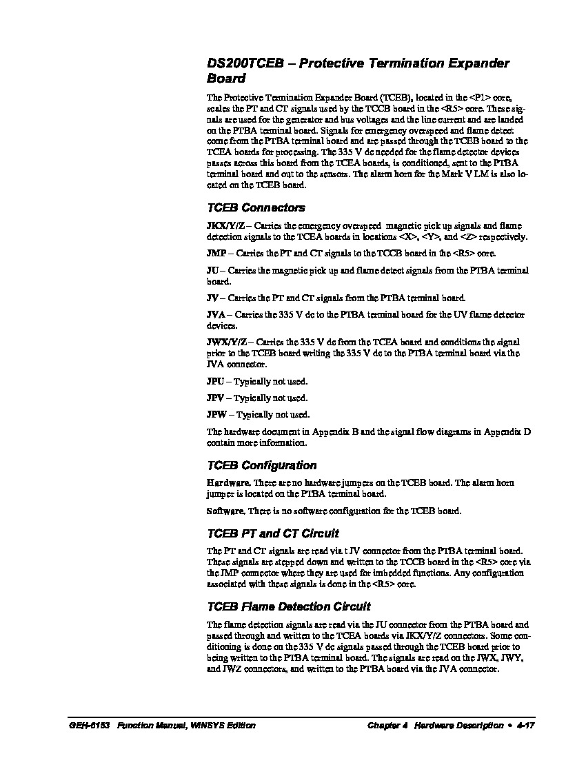
The GE Protective Termination Expander Board DS200TCEBG1 features 3 bayonet connectors, 4 signal transformers, and 1 26-pin connector. It also contains 4 10-pin connectors and 3 20-pin connectors. The 3 bayonet connectors are labeled JWX, JWY, and JWZ on the board. Cables with male bayonet connectors are designed to connect to them and there are some guidelines to consider. To connect a bayonet connector to the board, align it with the connector on the board and press it into place. When it is firmly connected, it clicks into place. To disconnect a cable with a bayonet connector, grasp the connector with your thumb and one finger. With the other hand support the board and keep it from moving. Pull out the cable and move it out of the way of the board. Luckily enough for the purposes of this DS200TCEBG1 personalized product page here, this DS200TCEBG1 Protective Termination Expander Board's connectors have all been listed in the DS200TCEBG1 instructional manual attached above in the manuals tab for your convenience. As explained before, all of this DS200TCEBG1 PCB's connectors correspond to their own factory-printed nomenclature labels. Some of this DS200TCEBG1 PCB's connectors include:
- The JKX/Y/Z TCEA Board Flame Detection and Magnetic Pick Up Signals Connector
- The JMP TCEB Board PT and CT Signals Connector
- The JU PTBA Board Flame Detection and Magnetic Pick Up Signals Connector
- The JV PTBA Board PT and CT Signals Connector
- The JVA PTBA Board 335 V dc Board Signals Connector
- The JWX/Y/Z TCEA, TCEB, and PTBA Boards 335 V dc Board Signals Connector
All of the aforementioned connectors in the assembly of this DS200TCEBG1 Mark V Series product offering have been named through a formulated combination of their specific factory-printed nomenclature labels, their Mark V Series compatible products and interfacing opportunities, and finally the specific signals that they were designed to transmit within the greater Mark V Series automated drive assembly. The JPU, JPV, and JPW connectors available to the assembly of this DS200TCEBG1 Board have not been named as such, as they only exist as vestigial structures not meant to be utilized or accessed during normative functionality of this DS200TCEBG1 product. Notice how the cable is routed in the interior of the drive and maintain the cable routing. Cable routing is important because it reduces interference in the signal cables and maintains the free flow of air. Interference occurs when power cables, which produce interference, run too close to signal cables. If signals are not being transmitted or received accurately, the drive will not operate effectively. Air flow cools the components of the drive and increases the length of time between when the components must be replaced. The 4 10-pin connectors are labelled JPU, JPV, JPW, and JMP. When the board is replaced, take time to inspect the defective board before you remove it. Create tags from masking tape or other means and write down the connector ID to which the cable is connected and tape the ID to the cable.


