About the DS200TCEBG1A
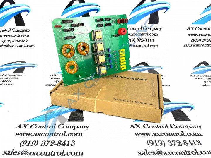
This DS200TCEBG1A printed circuit board was originally manufactured for General Electric's Mark V Turbine Control System Series, as indicated previously. The Mark V Series that this DS200TCEBG1A product offering belongs to, as you can probably tell by its extended series name, has specific applications in the control and management systems of compatible wind, steam, and gas turbine automated drive assemblies, and is considered a General Electric legacy series due to its eventual manufacturing discontinuation in the years following its initial release. While a legacy series, the Mark V Turbine Control System Series that this DS200TCEBG1A board is a member of is also one of the final General Electric Mark product series to make use of the company's patented Speedtronic control system technology. This DS200TCEBG1A printed circuit board is really better-definable through its official functional product description as a Protective Termination Expander Board, although the originally-produced PCB of this functionality to exist within the Mark V Series is the DS200TCEBG1A Protective Termination Expander Board missing this DS200TCEBG1A PCB's functional product revision.
Hardware Tips and Specifications
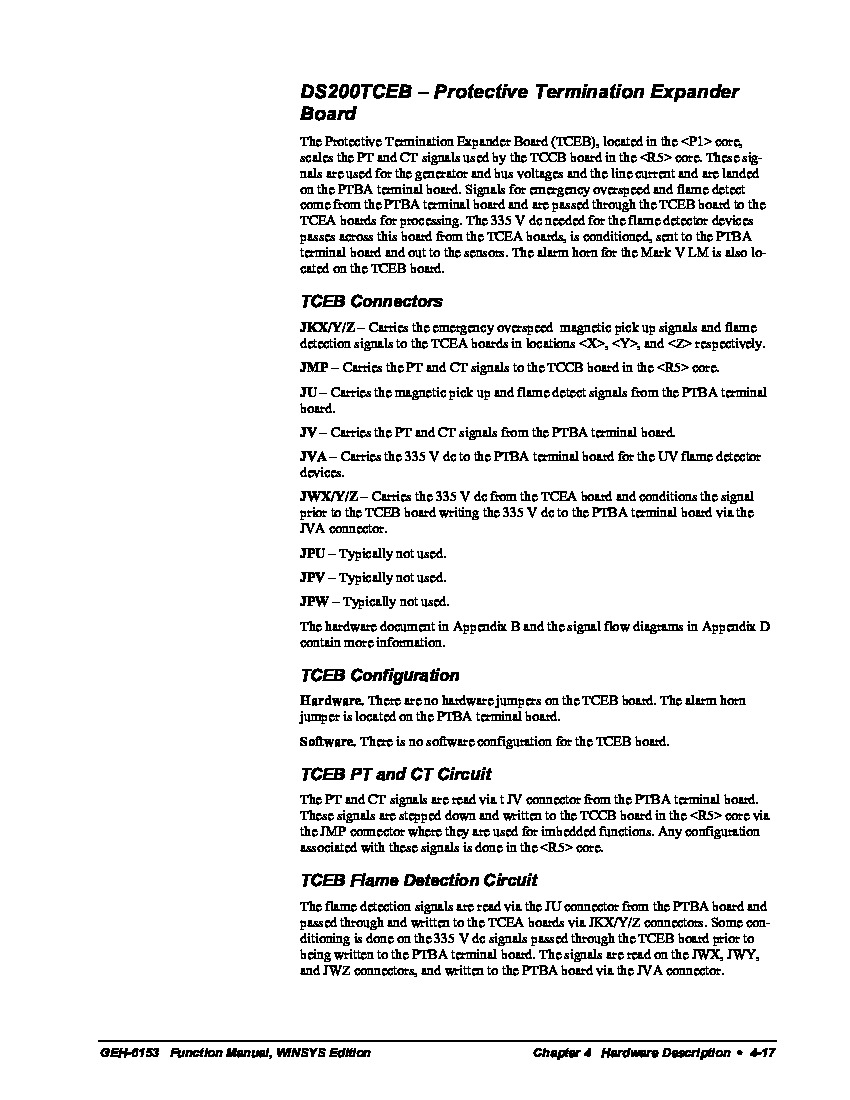
As with any product offering available to General Electric's Mark V Turbine Control System Series, this DS200TCEBG1A printed circuit board adopts its own necessary series of functionality-supporting and introducing hardware components. The GE Protective Termination Expander Board DS200TCEBG1A features 3 bayonet connectors, 4 signal transformers, and 1 26-pin connector. It also contains 4 10-pin connectors and 3 20-pin connectors. Because the GE Protective Termination Expander Board DS200TCEBG1A is populated with multiple heavy components it is designed with 8 screws holes to support the weight of the board when it is installed in the drive. The assembly of this DS200TCEBG1A Protective Termination Expander Board is also populated by various voltage-limiting hardware components standardized to the Mark V Series; including resistors, diodes, capacitors, and integrated circuits as identified in the DS200TCEBG1A instructional manual attached above. As identified in this aforementioned DS200TCEBG1A instructional manual, this DS200TCEBG1A PCB offers no software or hardware configuration-minded hardware components, although it does offer a series of connectors important to Mark V Series interfacing. Some of the specific connectors in this DS200TCEBG1A PCB's assembly include connectors with the factory-printed nomenclature labels JKX/Y/Z, JMP, JU, JV, JVA, JWX/Y/Z, JPU, JPV, and JPW. All of these connectors' specific functionality in terms of this DS200TCEBG1A board and its greater Mark V Series automated drive assembly are included in the above DS200TCEBG1A datasheet, spare the last three JPU, JPV, and JPW connectors. These connectors have not been functionally named as they exist as vestigial structures that typically go unused during normative functioning of the DS200TCEBG1A product.
Before you begin the task of removing the old DS200TCEBG1A board, notice where the old board is installed and plan to install the replacement board in the same location. Also notice where the cables are connected in the DS200TCEBG1A PCB's greater Mark V Series automated drive and create tags or labels with the ID of the connector it is connected to on the board. Only when you document where the cables attached to the new board can you disconnect them. Use a screwdriver to remove the screws that secure the DS200TCEBG1A PCB in the drive. Use one hand to turn the screwdriver and use the other hand to support the board in the drive. Keep all the screws and washers that you remove. If any screws drop into the bottom of the drive interior, retrieve the hardware before you proceed. A loose screw might make contact between DS200TCEBG1A electrical components and cause a short or electric shock or fire. This could lead to injury or extended downtime for the drive if additional repairs are required. If a screw is caught in a moving part, it might prevent the free movement of the part and cause damage to the motor or other parts.


