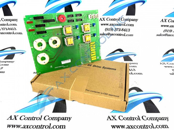
About the DS200TCEBG1B
This DS200TCEBG1B printed circuit board was originally manufactured by General Electric, as discussed before, to exist as a Protective Termination Expander Board within their Mark V Turbine Control System Series. As you may have been able to tell by its full functional series description, the Mark V Series that this DS200TCEBG1B product offering belongs to is focused on providing products for the control and management systems of compatible wind, steam, and gas turbine automated drive assemblies. This DS200TCEBG1B PCB's greater Mark V Series is additionally definable as one of the final General Electric product series to make use of the patented Speedtronic control system technology, a technology first released alongside the introduction of the Mark I Series in the later 1960s. This DS200TCEBG1B PCB's Mark V Series is finally additionally definable as a now-obsolete legacy product series, given its eventual necessary manufacturing discontinuation which took place in the years following its initial conception. Before making any final purchase decision on this DS200TCEBG1B Protective Termination Expander Board, it is important to realize that it has been edited from the DS200TCEBG1 parent printed circuit board product through its possession of a singular B-rated functional product revision.
Hardware Tips and Specifications
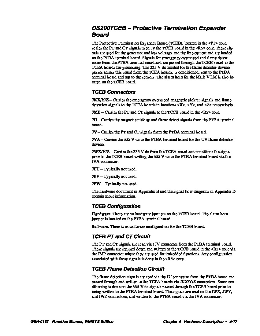
The General Electric Protective Termination Expander Board model DS200TCEBG1B features a complete total of 3 bayonet connectors, 4 signal transformers, and 1 26-pin connector. It also contains 4 10-pin connectors and 3 20-pin connectors. The GE Protective Termination Expander Board DS200TCEBG1B is limited in the diagnostic tools available if you suspect that the board is not operating as you expected. However, you can use the diagnostic tools available on the drive to gain insight into the board and all components in the drive. The diagnostics generate a report that details all warning, error, and trip conditions generated by the drive. The various connectors made available to the assembly of this DS200TCEBG1B Protective Termination Expander Board are described in detail in the DS200TCEBG1B instructional manual attached above, for your convenience. As with any individual hardware component in this DS200TCEBG1B printed circuit board product offering's assembly, this DS200TCEBG1B PCB's connectors are all identifiable through their own individual corresponding factory-printed nomenclature labels. Some of this DS200TCEBG1B PCB's various connectors include:
- The JKX/Y/Z TCEA Board Various Signals Connector
- The JMP TCCB Board PT and CT Signals Connector
- The JU PTBA Board Magnetic Pickup and Flame Detection Signals Connector
- The JV PTBA Board PT and CT Signals Connector
- The JVA PTBA Board UV Flame Detection Signals Connector
- The JWX/Y/Z TCEA, TCEB, and PTBA Boards 335 V dc Signals Connector
- The JPU Connector
- The JPV Connector
- The JPW Connector
All of the connectors listed above in the assembly of this DS200TCEBG1B product offering have been named through a combination of their individual factory-printed nomenclature labels, their Mark V Series compatible products, and finally their intended signals they transmit or their application. The JPU, JPV, and JPW connectors in this DS200TCEBG1B Board's assembly have not been named as such as they only exist as vestigial structures that typically go unused during normative functioning of this DS200TCEBG1B PCB and its greater Mark V Series automated drive assembly. A trip condition is a situation that causes the drive to automatically shut down to avoid damage or injury to the operator or others in the area. For example, if the interior of the drive becomes too hot and exceeds a limit, the drive will shut down. This might be caused by inadequate air flow in the immediate area around the drive, other equipment nearby overheating the air temperature, or air flow in the interior of the drive being restricted. The diagnostic report also provides details of the operation of the boards in the drive. From the report you can find the cause of the problem and how to resolve the issue. The report can be uploaded to a laptop that is connected to the drive through a serial cable. You can refer to the report as you resolve the issue and keep a record of the errors and warnings.


