About the DS200TCPDG1A
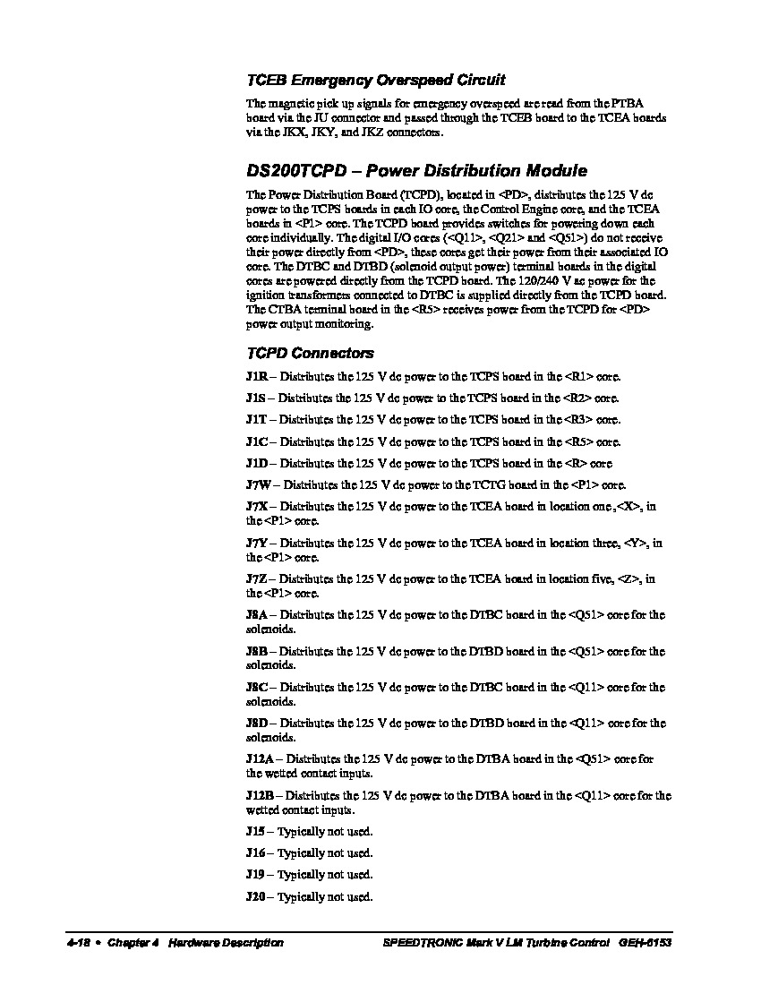
This DS200TCPDG1A printed circuit board product offering from General Electric, as specified just above, was originally designed and produced for the Mark V Turbine Control System Series. The Mark V Series that this DS200TCPDG1A PCB belongs to, as you can probably tell by its full extended series name, has specific applications in the management and control systems of popular and compatible wind, gas, and steam turbine automated drive assemblies. This DS200TCPDG1A PCB's greater Mark V Series is additionally considered to exist as a now-obsolete legacy GE product series, as it was discontinued due to its obsolescence in one of the many years past its initial GE release. This DS200TCPDG1A printed circuit board or PCB for short's greater Mark V Series, while obsolete, is still something of a highly-acclaimed General Electric Mark product series, as it is one of the brand's final-released series to incorporate the patented Speedtronic control system technology into its various offerings. This DS200TCPDG1A PCB is not the original product of its specific Mark V Series functional role; that would be the DS200TCPDG1 parent Power Distribution Board missing this DS200TCPDG1A PCB's A-rated functional product revision.
Hardware Tips and Specifications
As with any Mark V Series product available here, this DS200TCPDG1A PCB's specific functional role is adopted by its normal Mark V Series assembly's acceptance of a specific series of functionality-inducing hardware components and component specifications. The GE Power Distribution Board DS200TCPDG1A features 8 toggle switches, 36 fuses, and 4 signal wire terminals. It also has 36 OK LEDs and 1 10-pin connector. The fuses on the GE Power Distribution Board DS200TCPDG1A are housed in black plastic containers that obstruct the view of the fuse inside. The housing also protects the fuses from damage. In terms of customizable hardware, this DS200TCPDG1A printed circuit board product offering's assembly utilizes a singular manually-moveable hardware jumper and several styles of switch components. As with any individual hardware component available to the assembly of this DS200TCPDG1A Power Distribution Board, this DS200TCPDG1A PCB's jumper and switch components are all accompanied by their own respective factory-printed nomenclature labels, for convenient and standard identification purposes. The singular BJS jumper in the normal assembly of this DS200TCPDG1A device, as identified in the DS200TCPDG1A instructional manual embedded above, selects for the isolation of ground reference for systems with an external reference. Some of this DS200TCPDG1A PCB's switches include:
- The SW1 R1 Core Power Toggle Switch
- The SW2 R2 Core Power Toggle Switch
- The SW3 R3 Core Power Toggle Switch
- The SW4 R4 Core Power Toggle Switch
- The SW5 R5 Core Power Toggle Switch
- The SW6 P1 Core X Power Toggle Switch
- The SW7 P1 Core Y Power Toggle Switch
- The SW8 P1 Core Z Power Toggle Switch
Each of the above-listed switches in the normal assembly of this DS200TCPDG1A product offering have been named through a combination of their individual factory-printed nomenclature labels, their specific DS200TCPDG1A Board locations, and finally the specific applications or values they select for. To enable the operator to visually inspect the fuses, the board is populated with 36 green OK LEDs that indicate that the fuse intack. If the OK LED is off, it indicates that the fuse is blown and must be replaced. When you replace the fuse, make sure you use a fuse that is the exact type and rating as the fuse it is replacing. The written information that came with the board describes the type and rating of the fuse you must use. It is best practice to keep on hand a supply of the fuses you need for the board. This reduces the downtime needed to replace the fuse and restart the drive. To replace a fuse in the plastic housing, twist the top of the housing to access the fuse. With your fingers, remove the fuse and verify that it is blown. When the fuse is blown, the wire element in the glass tube in melted or broken, which indicates that the circuit is broken. To replace the fuse, align it with the housing and place it in the holder. Then, place the top on the housing and twist it closed.


