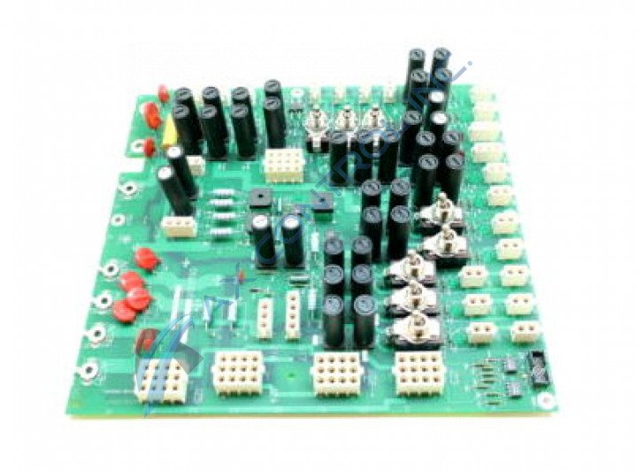
About the DS200TCPDG2B
This DS200TCPDG2B printed circuit board product offering from General Electric was, as mentioned before, originally designed and manufactured for placement in their Mark V Turbine Control System Series specifically as a Power Distribution Board. With this being true, this DS200TCPDG2B printed circuit board or PCB for short is not the originally-developed product of its specific Mark V Series functional role; that would be the DS200TCPDG2 parent Power Distribution Board missing this DS200TCPDG2B device's singular, B-rated functional product revision. This DS200TCPDG2B PCB's greater Mark V Series, as you have have been able to guess based on its full extended series name, has specific applications in the management and control systems of compatible and popular wind, steam, and gas turbine automated drive assemblies, and is considered a legacy General Electric Mark product series due to the eventual manufacturing discontinuation that took place in the many years following its initial release. While this DS200TCPDG2B printed circuit board product offering's greater Mark V Series is generally obsolete as a now-discontinued GE legacy series, it is still highly-sought within the automated industrial marketplace as it exists as one of the final General Electric product series to make use of the patented Speedtronic control system technology first seen with the release of the Mark I Series in the mid to later 1960s.
Hardware Tips and Specifications
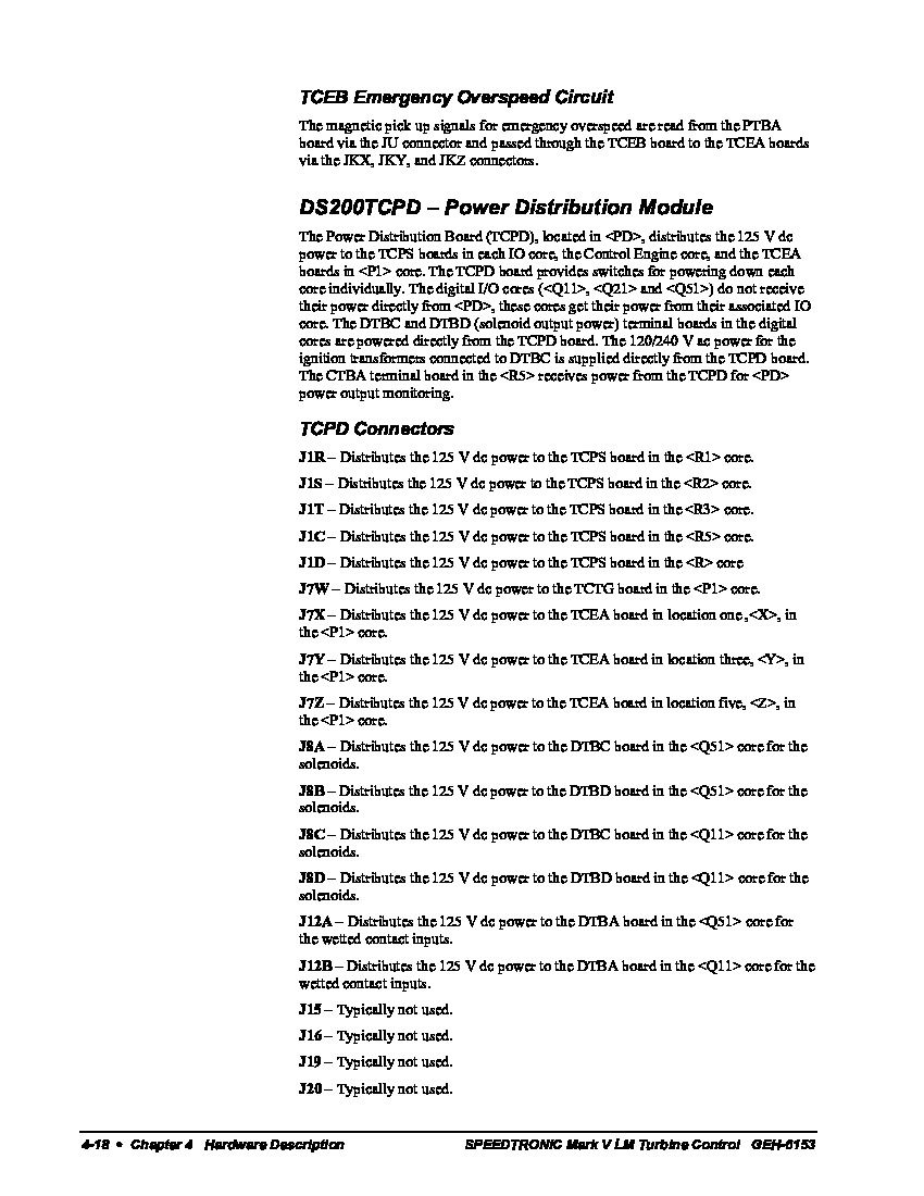
This DS200TCPDG2B printed circuit board product offering is introduced to its intended Mark V Series functionality as a Power Distribution Board through its normal Mark V Series assembly's internal acceptance of a unique series of hardware components and component specifications. It is something of a surprise this this DS200TCPDG2B PCB's DS200TCPDG2B functional product number asserts a normal Mark V Series assembly version, as this DS200TCPDG2B PCB's original, manual-included functional product description is that of a Power Distribution Module. The GE Power Distribution Board DS200TCPDG2B features 8 toggle switches, 36 fuses, and 4 signal wire terminals. It also has 36 OK LEDs and 1 10-pin connector. The installation instructions that shipped with the original board from the factory contain information about the signal wire terminals. It describes the function of each terminal and what signal wires to attach to it. For example it describes if the terminal receives signals from another board or if it transmits signals from another board. It also describes what information is carried by signal wires attached to it. Many of the specific connectors in the assembly of this DS200TCPDG2B printed circuit board product offering have been listed in the DS200TCPDG2B instructional manual attached above for your convenience, named for their functionality and specific DS200TCPDG2B Board locations. This is also true of the various switches available to the assembly of this DS200TCPDG2B device. Some of this DS200TCPDG2B PCB's switches include:
- The SW1 R1 Core Power Toggle Switch
- The SW2 R2 Core Power Toggle Switch
- The SW3 R3 Core Power Toggle Switch
- The SW4 R4 Core Power Toggle Switch
- The SW5 R5 Core Power Toggle Switch
- The SW6 P1 Core X Power Toggle Switch
- The SW7 P1 Core Y Power Toggle Switch
- The SW8 P1 Core Z Power Toggle Switch
Each of the above-listed switches in the normal assembly of this DS200TCPDG2B Mark V Series product offering have been named through a combination of their SW factory-printed nomenclature labels, their individual DS200TCPDG2B Board positioning, and the specific values that they select for. While many of this DS200TCPDG2B PCB's available switches have similar functionalities or selections, their descriptions above reveal varying DS200TCPDG2B Board locations. However, to replace the DS200TCPDG2B board it is not necessary to determine what signal wires to attach to the terminals. All the installer must do is attach the same wires to the same terminals on the replacement board. First examine the signal wire terminals and note that each terminal has an ID associated with it. The IDs are AC1N, AC1H, AC2N, and AC2H. Tag each wire with the ID of the terminal it is attached to. Use a tag that will not easily come off the wire. The wires are retained in the terminal with a screw. Use a screwdriver to loosen the screw and free the signal wire. Do the same for all the signal wires attached to the terminals. When you are ready to install the signal wires, first open the terminals by loosening the screws. Then, insert the wires and tighten the screws. Gently tug the signal wire to test that it is secure.


