About the DS200TCPSG1AEE
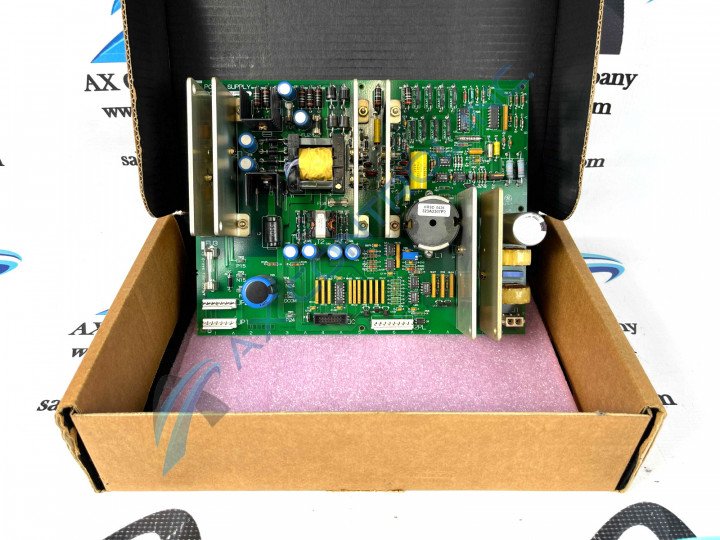
This DS200TCPSG1AEE printed circuit board product offering from General Electric is a crucial component member of the greater Mark V Series of turbine control systems and turbine control system components, as mentioned earlier. Within the Mark V Series drive assembly, this DS200TCPSG1AEE printed circuit board or PCB for short specifically is put to use in the crucial <R> core assembly. While this product's functional description as a Power Supply Board may not align perfectly with this product's TCPS functional acronym, this is the accurate manual-introduced description for this product. The DS200TCPSG1AEE printed circuit board was not the original Power Supply Board manufactured for General Electric's Mark V Series; that would be the DS200TCPSG1 parent printed circuit board missing this product offering's three significant product revisions.
Hardware Tips and Specifications
This DS200TCPSG1AEE Power Supply Board incorporates a series of necessary hardware component inclusions into its assembly to achieve its status as functional. The General Electric Power Supply DC Input Board model DS200TCPSG1AEE contains three fuses, one 16-pin connector, and one 9-pin connector. It also contains multiple test points. The GE Power Supply DC Input Board DS200TCPSG1AEE is installed in the board cabinet of the drive. The board cabinet compatible with this Mark V Series product is designed with a board rack with spaces for several boards to be installed. Each board is to be secured with screws and washers that hold the board in place; according to GE, it is important to tighten the screws securely but not too tight so that they crack or damage the board. The multiple test points are available on the DS200TCPSG1AEE printed circuit board for use by the servicer to test the circuits on the board, if a problem occurs. The test points are bare metal posts that enable a testing device to measure the signal present in the circuit and the activity occurring in the circuit. When you remove the board from the rack to use the test points or replace the fuses it is important to place the board on a static protective surface. Keep the static protective bag in which the board was shipped to you and always wear a wrist strap and clip the end of the strap to a bare metal surface, for surface voltage protection. This DS200TCPSG1AEE Mark V Series printed circuit board makes use of an elevated number of connectors in its assembly, including:
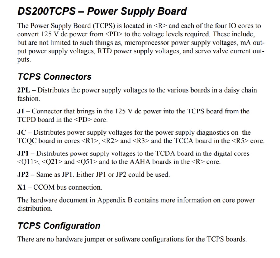
- The 2PL Power Supply Voltages Connector
- The J1 125 V dc TCPS Board Connector
- The JC TCCA/TCQC Boards Power Supply Voltages Connector
- The JP1 AAHA/TCDA Boards Power Supply Voltages Connector
- The JP2 AAHA/TCDA Boards Power Supply Voltages Connector
- The X1 CCOM Bus Connector
All of these different connectors are accompanied by their own shortened diagnostic labels from General Electric, and should receive some rudimentary level of basic protection from this printed circuit board's normal style of PCB coating, which coats individual hardware elements on a functional priority basis.


