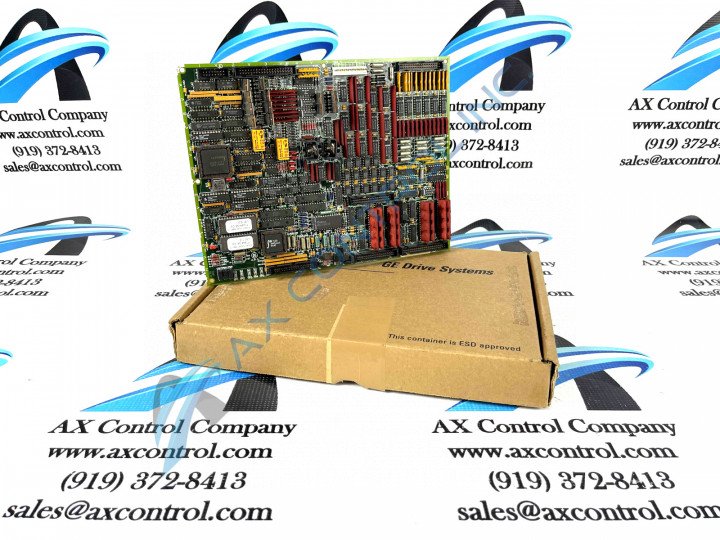
About the DS200TCQAG1BDC
This DS200TCQAG1BDC printed circuit board was originally manufactured for placement in General Electric's Mark V Turbine Control System Series, as alluded to above. As you can probably ascertain from its extended series name, the Mark V Series that this DS200TCQAG1BDC product offering belongs to has specific applications in the management and control systems of compatible wind, steam, and gas turbine automated drive assemblies, and is considered a legacy series due to its eventual manufacturing discontinuation in the years following its initial release. While the Mark V Series that this DS200TCQAG1BDC PCB belongs to is considered a legacy series, it also exists as one of the final General Electric product series to make use of the company's patented Speedtronic control system technology. This DS200TCQAG1BDC PCB is better definable functionally as an Analog IO Board, although the originally-produced Mark V Series product of this functionality is the DS200TCQAG1 parent Analog IO Board missing all three of this DS200TCQAG1BDC PCB's three significant revisions.
Hardware Tips and Specifications
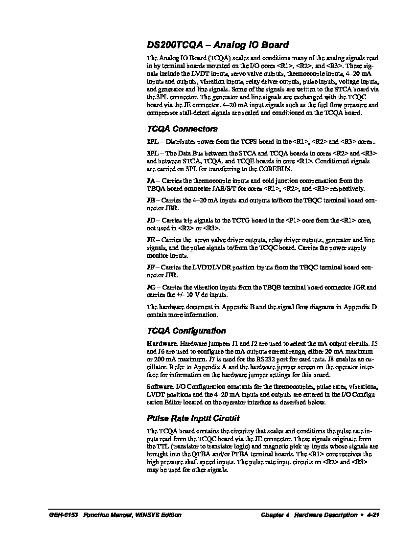
As with any Mark V Turbine Control System Series product, this DS200TCQAG1BDC offering makes use of its own set of functionality-introducing hardware component inclusions and specifications. The GE RST Analog I/O Board DS200TCQAG1BDC contains four 34-pin connectors, two 40-pin connectors, and six jumpers. The DS200TCQAG1BDC board is also integrated with 6 LED lights. The six jumpers enable the board to be configured for the exact processing requirements of the site and are typically set when the board is installed in the drive. Some of the jumpers are not for use in configuration and are only intended for use by the factory for quality control purposes. For example, they allow for testing of a particular circuit, function, or other factor. Also present in the assembly of this DS200TCQAG1BDC PCB are various hardware components intended for voltage limitation and suppression; Mark V Series-standardized parts such as capacitors, resistors, and integrated circuits. The aforementioned connectors in the assembly of this DS200TCQAG1BDC product offering have been listed in detail in this DS200TCQAG1BDC PCB's original instructional manual attached above. Some of the DS200TCQAG1BDC PCB's connectors include:
- The 2PL TCPS Power Distribution Connector
- The 3PL STCA and TCQA Boards COREBUS Conditioned Signals Connector
- The JA TBQA Board Thermocouple Inputs and Cold Junction Signals Connector
- The JB TBQC Board Input and Output Signals Connector
- The JD TCTG Board Trip Signals Connector
- The JE TCQC Board Various Outputs and Pulse Signals Connector
- The JF TBQC Board LVDT/LVDR Position Input Signals Connector
- The JG TBQB Board Vibration Input Signals Connector
All of the above-listed connectors in the assembly of this DS200TCQAG1BDC product offering have been named through a combination of their factory-printed nomenclature labels, Mark V Series interfacing opportunities, and functionality in terms of the DS200TCQAG1BDC PCB's greater Mark V Series automated drive assembly. The information that comes with the original DS200TCQAG1BDC board explains the use of its available six jumpers. But, when you are replacing the board the best practice is to compare the two boards side-by-side and set the jumpers on the replacement board exactly the same as on the old board. To mimic the jumper configuration, first make sure all power is removed from the drive by disabling the power supplies to the drive. This is often accomplished by removing the fuses from the power supply. Only a qualified person can perform this activity due to the high-voltage surrounding the power supplies and the drive. Also, the person must be familiar with the DS200TCQAG1BDC PCB's cable routing, emergency shut offs, and devices in the immediate area around the drive. Use testing equipment to test for the presence of power in the drive. The controls on the tester must be set for the task and the tester must be designed for testing high-voltage current.


