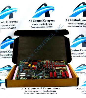
About the DS200TCQAG1BEC
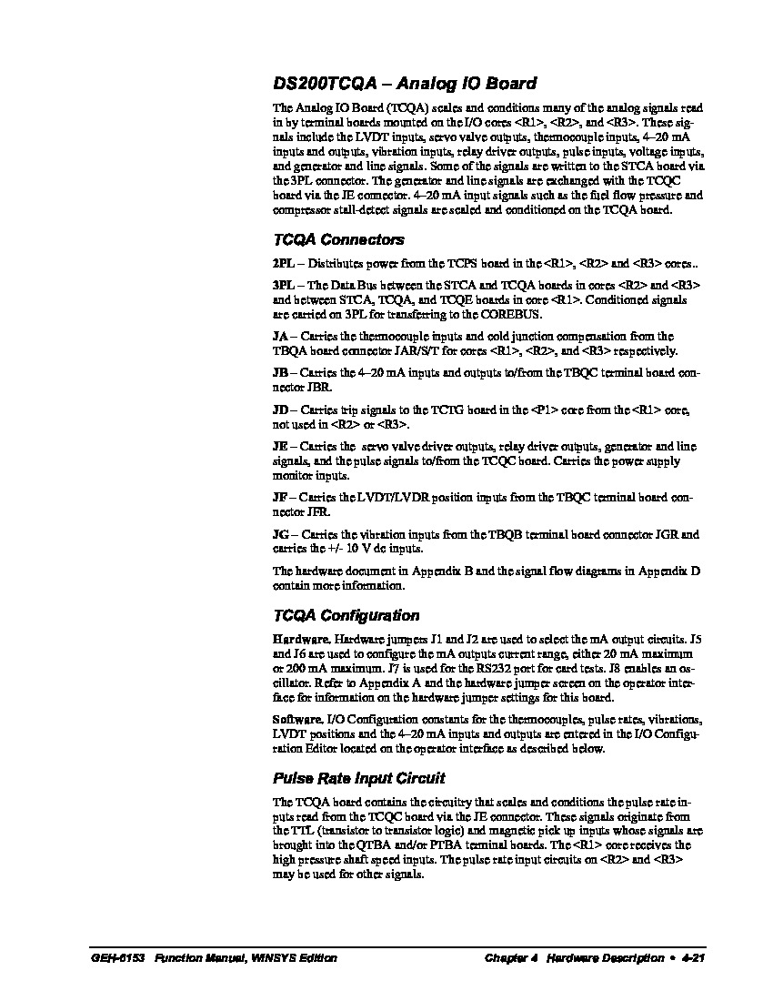
This DS200TCQAG1BEC printed circuit board was originally manufactured for use in General Electric's Mark V Turbine Control System Series, as mentioned before. As hinted at by its full extended series name, the Mark V Series that this DS200TCQAG1BEC PCB belongs to has specific applications in the management and control systems of compatible wind, steam, and gas turbine automated drive assemblies, and is one of the final General Electric Mark product series to incorporate the patented Speedtronic control system technology. This DS200TCQAG1BEC printed circuit board product offering is better-classifiable by its official functional product description as an Analog IO or Analog Input/Output Board, as included in the DS200TCQAG1BEC instructional manual attached in the manuals tab above.
Hardware Tips and Specifications
The GE RST Analog I/O Board DS200TCQAG1BEC contains four 34-pin connectors, two 40-pin connectors, and six jumpers. The GE RST Analog I/O Board DS200TCQAG1BEC also has 6 LEDs that are arranged together on the board and provide an indication of the health and activity of the board. For example, the LEDs might indicate that power is present in the board or that processing is taking place. The LEDs are red in color when lit. In addition to the various LED indicators offered to the assembly of this DS200TCQAG1BEC product offering, it also makes use of a series of different Mark V Series connectors; important in establishing various interface connections with other printed circuit boards within the overall; Mark V Series automated drive assembly. Some of the connectors made available to this DS200TCQAG1BEC Analog IO Board's assembly include:
- The 2PL TCPS Board Power Distribution Connector
- The 3PL STCA and TCQA Boards Data Bus Conditioned Signal Connector
- The JA TBQA Board Themocouple Inputs and Cold Junction Compensation Connector
- The JB TBQC Board Inputs and Outputs Connector
- The JD TCTG Board Trip Signals Connector
- The JE TCQC Board Output and Pulse Signals Connector
- The JF TBQC Board LVDT/LVDR Position Input Signals Connector
- The JG TBQB Board Vibration Input Signals Connector
Each connector in the assembly of this DS200TCQAG1BEC product offering has been named through a combination of their own respective factory-printed nomenclature labels, their Mark V Series interfacing potentials, and their application and functionality in terms of the DS200TCQAG1BEC Board and its greater Mark V Series automated drive assembly. If you view the LEDs in this DS200TCQAG1BEC PCB's assembly and you suspect that a problem is indicated, you can use the diagnostic tools in the drive for a complete look at the processing in the board. Access the diagnostics from the control panel on the drive and use the tools to produce a diagnostic report. You can scroll through the report on the control panel display or save the report as a file. The file can be saved on a laptop and compared to other diagnostic reports. To save the diagnostic file, connect a serial cable to the serial connector on the drive and to a laptop. Select to download the file on the drive and receive the file on the laptop. Make sure the serial port on the laptop is configured properly. Download the diagnostic tool on the laptop and use it to view the report file. The report will indicate the cause of the problem with the drive. After you resolve the issue, you can produce a new diagnostic report and compare the two reports to determine if the issue is resolved.


