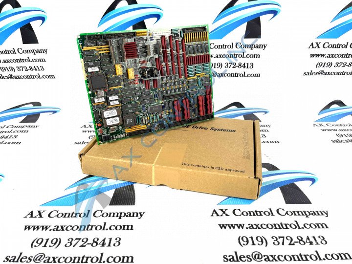
About the DS200TCQAG1BGE
This DS200TCQAG1BGE General Electric printed circuit board product offering is, as mentioned above, more explicitly-definable by its true functional role as an Analog IO Board within the greater Mark V Turbine Control System Series. As you could have probably guessed from its full name, the Mark V Series that this DS200TCQAG1BGE printed circuit board or PCB for short belongs to has crucial applications in the control and management systems of wind, gas, and steam turbine automated drive assemblies. The Mark V Turbine Control System Series is one of the final General Electric product series to feature their patented Speedtronic technology first introduced with the rollout of the Mark I in the late 1960s; and is considered a legacy General Electric series as it is no longer in active production by the original retailer. This DS200TCQAG1BGE PCB is truly better-definable by its factory-printed instructional manual's functional product description as an Analog IO or Analog Input/Output Board, although it is not the original product with this attempted functionality to feature within the Mark V Series. The Mark V Series' original Analog IO Board is the DS200TCQAG1 parent printed circuit board missing all three of this DS200TCQAG1BGE product's three significant product revisions.
Hardware Tips and Specifications
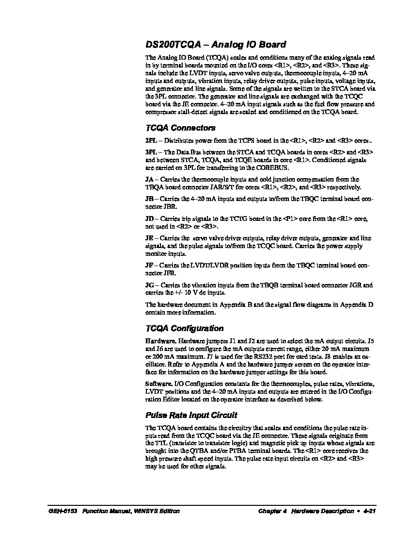
Given this DS200TCQAG1BGE board's specific intended Mark V Series functionality as an Analog IO Board, it should come as no true surprise that this product utilizes its own series of hardware component inclusions and specifications to achieve this functionality. The GE RST Analog I/O Board DS200TCQAG1BGE contains four 34-pin connectors, two 40-pin connectors, and six jumpers in its assembly. The DS200TCQAG1BGE board also has 6 LEDs, which have been included for diagnostic purposes of normal Mark V Series drive conditions and functional faults. The 34-pin connectors and 40-pin connectors on the GE RST Analog I/O Board DS200TCQAG1BGE are attached to ribbon cables and they send and receive signals to the other boards and components in the drive. This DS200TCQAG1BGE Analog IO Board makes use of several integrated circuits in its assembly, as described in detail in available Mark V Series instructional manual materials. Some of these generally voltage-limiting integrated circuits include:
- The Pulse Rate Input Circuit
- The TCQA 4-20 mA Input Circuits
- The TCQA 4-20 mA Output Circuit
- The TCQA Thermocouple Circuit
- The TCQA LVDT/R Circuit
- The TCQA Seismic Vibration Circuit
- The TCQA Generator And Line Circuit
All of these aforementioned circuits in the assembly of this DS200TCQAG1BGE Analog IO Board have been named through an analysis of their functional relevance to this DS200TCQAG1BGE printed circuit board product and its greater Mark V Series automated drive assembly. The connectors in the assembly of this DS200TCQAG1BGE Analog IO Board and their specific selections are also displayed in original General Electric instructional manual materials attached above in a similar manner.
Because the cables in the assembly of this DS200TCQAG1BGE PCB carry control signals, you must be careful to route ribbon cables away from power cables and away from other components in the drive that contain high voltage. This can cause interference in the signals which might lead to intermittent problems. A good policy is to route the cables exactly as they were routed when the original board was installed. When you connect or disconnect a ribbon cable in this DS200TCQAG1BGE board's assembly you must follow guidelines to prevent damage to the cables. Be aware that the fine wires that comprise the ribbon cable are attached to the plastic connector on the end of the cable. Any stress on the cable might cause the connector to detach from the ribbon so care must be taken. When you disconnect the ribbon cable, use one hand to hold the plastic connector and with the other hand support the board. Pull the ribbon cable out of the board. To reconnect the ribbon cable, use one hand to hold the plastic connector and press the connector into the connector located on the board. Never disconnect it by pulling on the ribbon cable which puts stress on the fine wires.


