About the DS200TCQCG1ADB
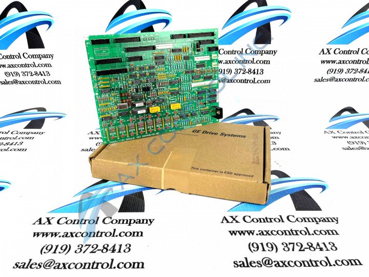
This DS200TCQCG1ADB printed circuit board, as described above, hails from General Electric's Mark V Turbine Control System Series, which exists as a now-obsolete legacy product series due to its eventual manufacturing discontinuation that took place in the many years following its initial release. While this DS200TCQCG1ADB PCB's greater Mark V Series is considered a legacy product series, it concurrently exists as one of the final General Electric Mark product series to incorporate the patented Speedtronic control system technology into its various offerings. The Speedtronic technology featured in this DS200TCQCG1ADB product and the rest of its Mark V Series was originally released for public consumption during the rollout of the earlier Mark I Series in the late 1960s. This DS200TCQCG1ADB Device's Mark V Series has products with specific applications in the control and management systems of compatible wind, steam, and gas turbine automated drive assemblies. This DS200TCQCG1ADB printed circuit board product offering is officially deemed an Analog IO Expander Board in its original Mark V Series instructional manual materials, although it is additionally referred to in fringe documentation as an RST Overflow Board. This DS200TCQCG1ADB Analog IO Expander Board is not the original mark V Series product of its intended functionality; that would be the DS200TCQCG1 parent printed circuit board missing all three of this DS200TCQCG1ADB PCB's three significant product revisions.
Hardware Tips and Specifications
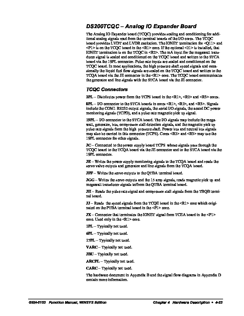
This DS200TCQCG1ADB PCB's Analog IO Expander Board is introduced through its internal assembly's acceptance of a unique series of hardware components and component specifications. The GE RST Overflow Board DS200TCQCG1ADB is populated with 24 jumpers and 3 40-pin connectors. It also has 3 34-pin connectors and 1 16-pin connector. The ID assigned to the 16-pin connector is JC. The IDs assigned to the 40-pin connectors are JFF, JE, and 6PL. The board also has 2 3-pin connectors. The IDs for the 3-pin connectors are VARC and JX. The specific applications for each connector in the assembly of this DS200TCQCG1ADB printed circuit board product offering are listed in the DS200TCQCG1ADB instructional manual stored above for your convenience. Like any individual hardware component in this DS200TCQCG1ADB Board's assembly, each of these connectors is accompanied by its own factory-printed nomenclature label for simplistic identification purposes. Some of the various Mark V Series connectors in the assembly of the DS200TCQCG1ADB Analog IO Expander Board include:
- The 2PL TCPS Board Power Distribution Connector
- The 8PL STCA Board Various Signals Connector
- The 19PL STCA Board I/O Signals Connector
- The JC TCPS Board Board Signals Connector
- The JE TCQA Board Outputs and Line Signals Connector
- The JFF QTBA Board Servo Outputs Connector
- The JGG QTBA Board Servo Outputs Connector
- The JH TBQB Conversion Signals Connector
- The JJ TCQE Board Speed Signals Connector
- The JX TCEA Board IONET Signal Termination Connector
Each of the above-listed connectors in the assembly of this DS200TCQCG1ADB PCB have been named through a combination of their specific factory-printed nomenclature labels, their Mark V Series interfacing potentials and compatible products, and finally the signals they transmit in the DS200TCQCG1ADB PCB's assembly and its greater Mark V Turbine Control System Series automated drive assembly. The connector IDs are useful when you plan to replace the GE RST Overflow Board DS200TCQCG1ADB. To install the new board and ensure that it will perform exactly like the board it is replacing, it is necessary to connect the cables to the same connectors. With multiple cables connected to the board, you must ID the cables to know where they are connected on the board being replaced before you disconnect them. Use strips of masking tape or stickers that can be temporarily attached to the cables and write down the ID of the connector it is attached to. You might find that the new board is a later version of the board and has the connectors located in different positions. This to accommodate circuit design changes. It might have components that look different also. However, the board will operate the same despite the differences. Due to product testing in many different environments, you can be sure the board has been tested and verified that it will operate the same way. The installer must also set the jumpers to match the positions set on the board it is replacing.


