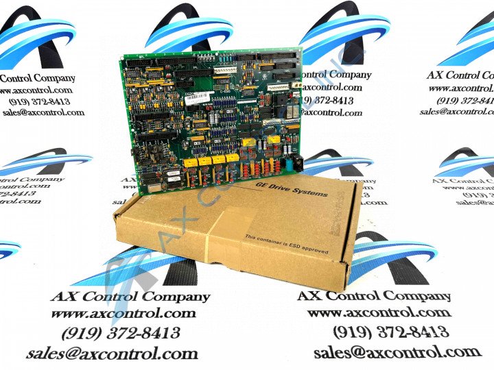
About the DS200TCQCG1B
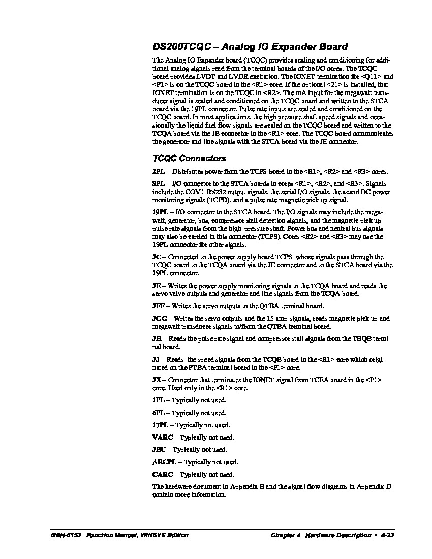
This DS200TCQCG1B printed circuit board product offering was originally, as alluded to above, manufactured by the trusted General Electric automated industrial retailer, specifically for placement in their Mark V Turbine Control System Series. The Mark V Series that this DS200TCQCG1B printed circuit board or PCB for short belongs to, as proven in the above-attached full extended series name, has specific applications in the management and control systems of popular and compatible steam, gas, and wind turbine automated drive assemblies, and can be considered a now-defunct legacy product series, given its eventual manufacturing discontinuation due to obsolescence that took place in one of the many years beyond its initial General Electric rollout. This DS200TCQCG1B PCB's greater Mark V Turbine Control Systems Series is still something of an acclaimed General Electric Mark product series despite its legacy status; most likely due to its inclusion of the Speedtronic control system technology across a range of its various products. The Speedtronic control system technology seen in this DS200TCQCG1B product offering and its greater Mark V Series was originally introduce in the later 1960s with the inception of the Mark I Series. This DS200TCQCG1B printed circuit board is definable as an Analog IO Expander Board based on this functional descriptions' insertion in Mark V Series instructional manual materials, although the originally-produced product of this intended functionality is the DS200TCQCG1 parent Analog IO Expander Board.
Hardware Tips and Specifications
Given the fact that this DS200TCQCG1B printed circuit board product offering exists as a Mark V Series functional product, it possesses a specific functionality only accessible by its internal assembly's acceptance of a specific and unique series of hardware components and component specifications. The GE RST Overflow Board DS200TCQCG1B is populated with 24 jumpers and 3 40-pin connectors. It also has 3 34-pin connectors and 1 16-pin connector. The ID assigned to the 16-pin connector is JC. The IDs assigned to the 40-pin connectors are JFF, JE, and 6PL. The board also contains test points that are useful if the board stops functioning entirely or if some of the functions remain operational while others seemed to have stopped functioning or they provide inadequate results. In terms of voltage limitation and suppression, this DS200TCQCG1B printed circuit board's voltage protection strategy involves its normal Mark V Series assembly's adoption of a series-standardized collection of voltage-limiting hardware components such as various styles of capacitors, resistors, transistors, and diodes, as well as several specialized integrated circuits. Given the fact that this DS200TCQCG1B PCB belongs to the now-obsolete Mark V Turbine Control System Series, its originally-collected instructional manual materials are largely unavailable online for the purposes of this DS200TCQCG1B personalized product page. With this being true, the DS200TCQCG1B functional product number itself can be considered a strong source of DS200TCQCG1B Board hardware information; coding for specific details in a series of consecutive functional naming chunks. For example, the DS200TCQCG1B functional product number begins with the DS200 series tag describing this DS200TCQCG1B Board's normal Mark V Series assembly and domestic manufacture location. Some of the other hardware details embedded in the DS200TCQCG1B functional product number itself include this Mark V Series PCB's:
- TCQC functional product acronym
- Group one Mark V Series product grouping
- Normal PCB coating style
- B-rated functional product revision
A qualified servicer has knowledge of the drive and also understands how to work safely around high voltage devices. The qualified servicer understands how to assess the safety of the area surrounding the drive before starting to service the drive. For example, the servicer must verify that the floor is dry and clear of debris. Any water or moisture must be cleared and detergents can be used to clean any oil or grease. Any ungrounded power cords must be removed from the area because of the hazard of electric shock. The servicer must locate and verify that the emergency power shut offs are nearby and operational. Finally, the servicer must have a partner or associate nearby in case an emergency situation occurs. If needed, the associate can call for help, pull the emergency shut off, or assist the servicer. The qualified servicer is also equipped with the necessary testing devices. The devices must be safe to use around high voltage and must be calibrated to provide accurate values for the testing being performed.


