About the DS200TCQCG1BJF
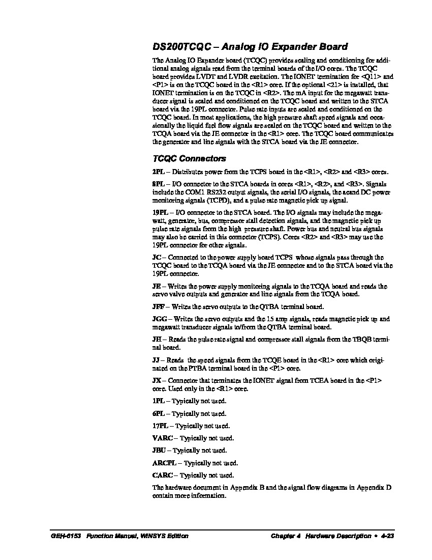
This DS200TCQCG1BJF circuit board from General Electric is a bit of an enigma, given the numerous different functionalities that it is referred to by in original General Electric instructional documentation. This DS200TCQCG1BJF printed circuit board or PCB for short is deemed as both a RST Overflow Board and a Analog IO Expander Board. With that being said, most official General Electric instructional manual materials concerning this Mark V turbine control system series product deem it to be an Analog IO Expander Board, so that is how it will be referred to on this individualized product page for the most part.
Hardware Tips and Specifications
As with any Mark V Series product offering, this DS200TCQCG1BJF Analog IO Expander Board necessitates the inclusion of several unique and specific hardware components and component specifications in its internal assembly; the first of which being its three product revisions. Two of these three revisions are aimed towards bettering the general functionality and performance specifications of the DS200TCQCG1 parent printed circuit board, while the third is for aesthetic and durability purposes.
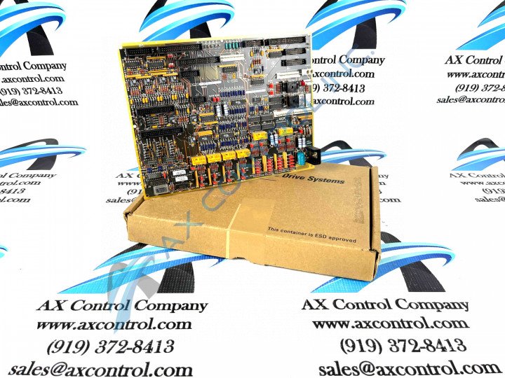
The GE RST Overflow Board DS200TCQCG1BJF is populated with 24 jumpers and 3 40-pin connectors. It also has 3 34-pin connectors and 1 16-pin connector. Each individual hardware element in the assembly of this Analog IO Expander Board is accompanied by an individual reference designator ID. The ID assigned to the 16-pin connector is JC. The IDs assigned to the 40-pin connectors are JFF, JE, and 6PL. The GE RST Overflow Board DS200TCQCG1BJF also contains several relays that switch circuits on the board on and off. The relays require no maintenance and are soldered to the board with leads. The IDs of the 34-pin connectors are JFF, 1PL, and JA. The 40-pin connectors and 34-pin connectors attach to ribbon cables that connect the Analog IO Expander Board DS200TCQCG1BJF to other boards and components in the drive. When you replace the board it is important to the maintain the cable routing that is arranged in the drive for the cables. Because the ribbon cables carry signals improper routing can introduce interference from power cables that are routed too close to the signal cables. Interference happens when signal and power cables are routed parallel to each other, so generally, it is best keep them separated. If they must come in contact to each other, have them cross each other at a 90 degree angle only.


