About the DS200TCQFG1A
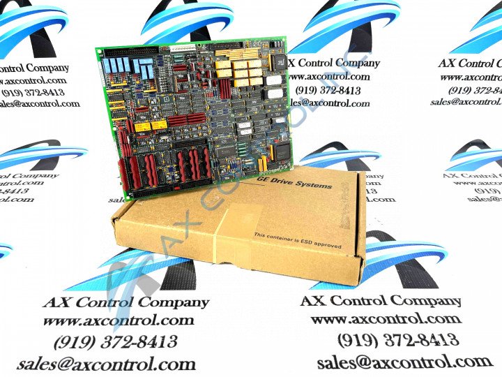
The DS200TCQFG1A is a GE TC2000 Analog I/O Extender Board. Unfortunately, due to a lack of manual material available online, it is something of a mystery as to which exact series the DS200TCQFG1A belongs to, although its original retailer of GE Drive Systems suggests a EX2000 series board. This PCB does have relevant information available, however, through a careful examination of its product number and a detailed visual inspection. This is a modified version of the original DS200TCQF module, that includes a singular revision.
Hardware Tips and Specifications
The GE TC2000 Analog I/O Extender Board DS200TCQFG1A is populated with 7 jumpers and 2 50-pin connectors. It also has 1 34-pin connector and 1 9-pin connector. The ID assigned to the 34-pin connector is JA. The IDs assigned to the 50-pin connectors are JUU and JB. During normal processing, the GE TC2000 Analog I/O Extender Board DS200TCQFG1A uses electronic relays to turn circuits off and on. The relays are present on the board and are soldered to the board with wire leads.
The board also is populated with 6 LEDs that are arranged horizontally on the board. They are visible to the operator when the board is installed in the board cabinet inside the drive. The LEDs are green in color when lit and they are OK LEDs. That is, when the LEDs are lit it indicates that the function that it represents is receiving current and is operating normally. Each of the 6 LEDs is associated with a circuit or function on the board. When the LEDs flash, it indicates that normal processing is taking place. This provides the operator with a quick method of determining the health of the board while the drive is in operation.
The GE TC2000 Analog I/O Extender Board DS200TCQFG1A is populated with a programmable logic device that provides a processing function necessary to the operation of the board. The programmable logic uses the firmware and programming code embedded on the erasable programmable read only memory (EPROM) module installed on the board.
Installation Tips and Specifications
While a number of Hardware Specifications are always important to consider before making a purchase of this DS200TCQFG1A and any printed circuit board, it is important to heed a guided installation strategy for safe and effective TCQF board initialization. For starters, when attempting the replacement or installation of any printed circuit board, it is crucial to shut off all input and output power present in the greater series drive assembly, whichever assembly that may be. This is crucial due to the existence of potentially lethal surface voltages on any General Electric, GE Industrial Control, GE Drive Systems, GE Energy, and other GE shell company component PCBs. In addition to the necessary absence of any surface voltages, it is recommend that the TCQF board installer makes use of a ground strap for additional voltage protection purposes; during the entirety of the DS200TCQFG1A PCB's installation.
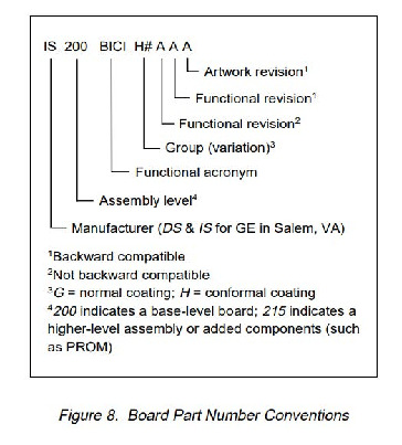
Beyond the various measures recommended by General Electric for safe installation of their DS200TCQFG1A product, it is important to recognize this Analog I/O Extender Board's revision history. As mentioned before, this PCB has a singular revision. Classified as a functional revision, this DS200TCQFG1A product number reveals a functional revision graded at an "A" rating through the final included digit of A. A more detailed analysis of this part's specialized part number has been made available for your convenience above in our "manuals" tab.


