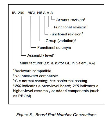
About the DS200TCRAG1AAA
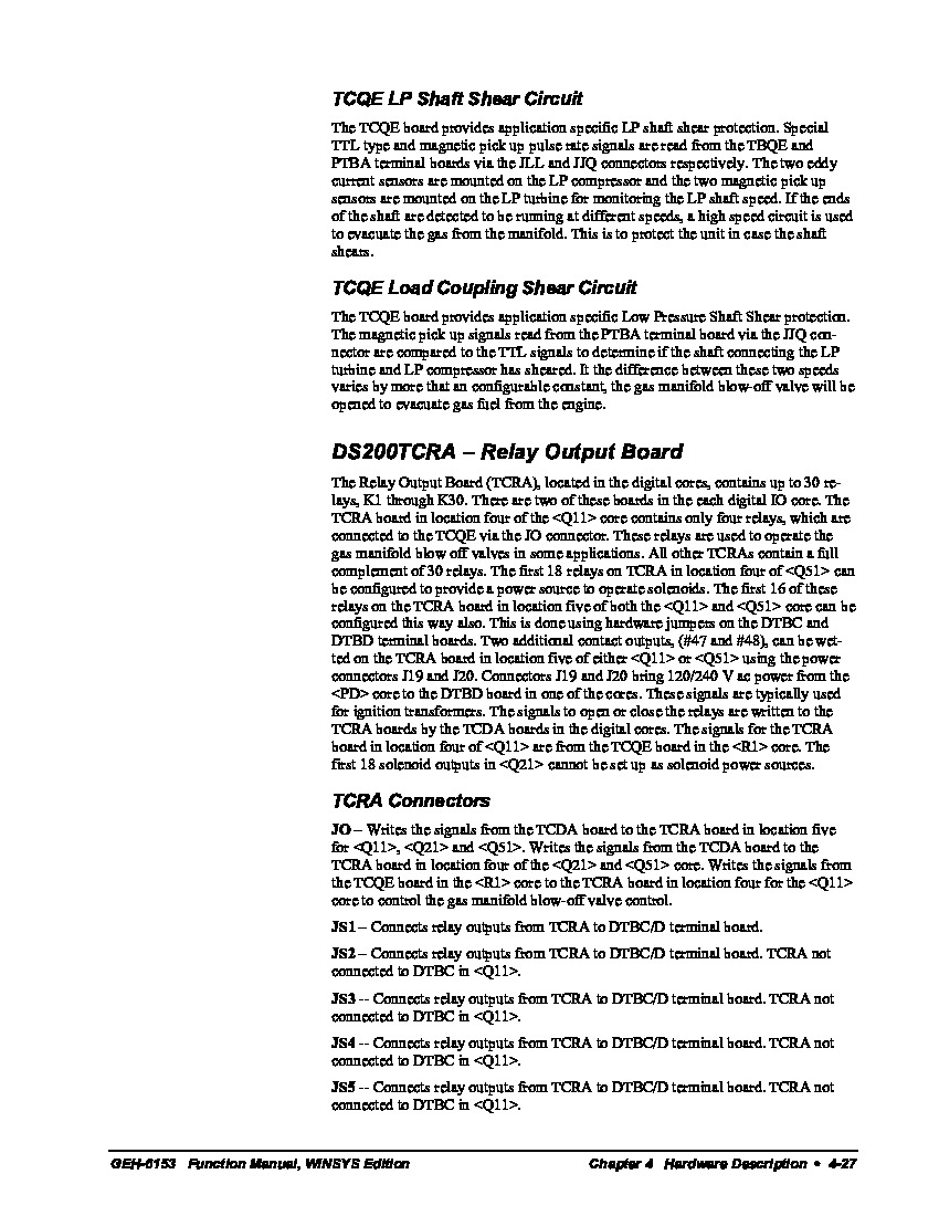
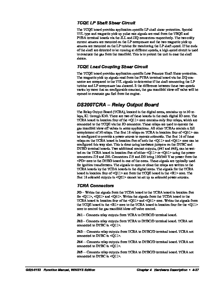
The GE Relay Output board DS200TCRAG1AAA exists as part of General Industrial Systems' Mark V series of LM Turbine Control. In some cases this PCB may be installed for use in gas manifold blow off valve operation in some applications, although this is usually limited to boards with less than the 30 plug-in relays present here. This board may be installed in order to introduce a power source to operate PCB solenoids, or for the opening and closing of relays important to bringing 120/240 VAC power to an attached DBTD board. This particular printed circuit board has a single access point for convenient system and data access.This product, as a vintage or refurbished GE Mark V series item, is available for both repair and replacement here at AX Control, with a standard lead repair time of one to two weeks on any repair. This product is eligible for our extended 3-year warranty upon purchase, as it is consider a printed circuit board.
Hardware Tips and Specifications
It is important to consider a number of hardware specifications unique to the DS200TCRAG1AAA relay output board before making any purchase.
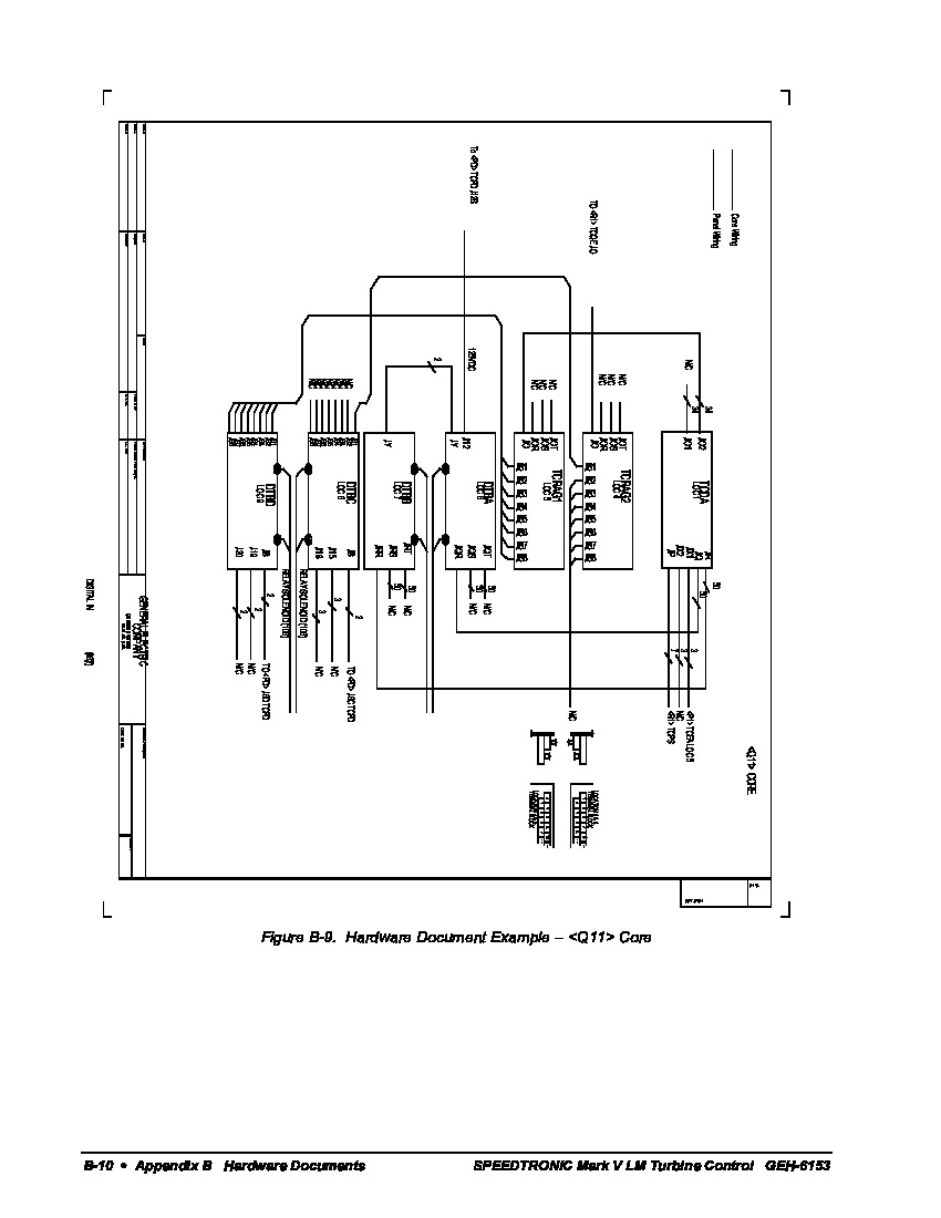
The GE Relay Output Board DS200TCRAG1AAA is populated with 30 plug-in relays. It also has 4 34-pin connectors and 4 12-pin connectors. The IDs assigned to the 34-pin connectors are JOR, JOS, JOT, and JO. The IDs assigned to the 12-pin connectors are JS3, JS4, JS5, and JS6. Each individual relay attached to the face of this relay output board is labeled with voltage specifications, letting the drive administrator know that the relay can handle voltages of 10A, 240 VAC, or 28 VDC. The part number for the DS200TCRAG1AAA's individual relays can also be defined as CDR402CQQSN. DS200TCRAG1AAA, when configured correctly, is connected to a DS200DTBC contact output termination module through the use of the TCRA's 30 available relays. This termination module is additionally affixed to four contact output relays available on the base plate of the DS200TCRAG1AA. This is not the only PCB component part compatible with the DS200TCRAG1AAA; as the contact output expansion termination module DS200DTBD also makes use of TCRA relays in three positions.
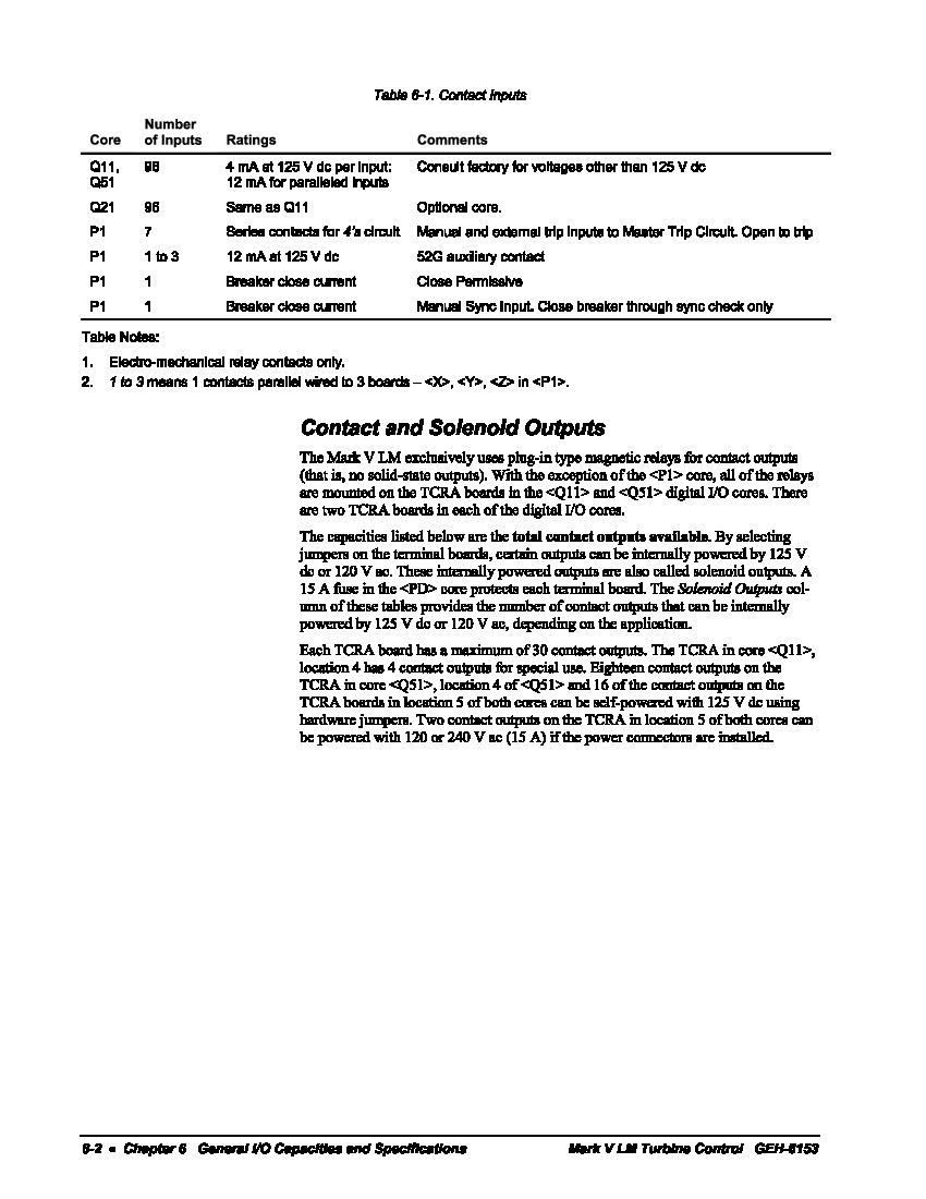
Any one of the relays present on the TCRA component board are operated when prompted by signals from the greater assembly's CSP. These relays are collected in the assembly's STCA boards, which begin a series of processes begin, recylcing this information unto the assembly's TCDA board, which energizes the aforementioned relays as necessary. The relay responsible for opening and closing, in this instance, is connected to both the DTBC and the DTBD terminal boards through the use of "JS" connectors. More information concerning the entirety of this process is available online in the GE Industrial Systems' GEH-6153 Function Manual, WINSYS Edition, attached above through our "manuals" tab.
When you receive the GE Relay Output Board DS200TCRAG1AAA it is important to guard against static build up when you handle the board and during the time it is stored before you install it, and as with any circuit board, it is paramount to treat the product with overwhelming caution and respect. When the box is delivered to your location, be sure to:
- Inspect the box to verify that during shipping it was not damaged by careless handling. Ensure the box was not crunched, dented, or ripped open.
- Please also make a quick scan of the packaging for signs that it has leaked on or sat in a puddle of liquid.
- After this basic check on the product's packaging, move the packing material from the top of the box.Open the box and gather all the flyers, loose paper, and other instructions.
- This PCB should be removed from the box carefully with two hands, while still in the static-protective bag.
- If you plan to store the board before you install it, place it back in the box, close the lid, and store it in a clean and dry location that is secure. If you plan to install the board in the drive immediately, place the board on a flat clean surface.
- Put on a wrist strap and with a sharp blade open the static-protective bag.
- Hold the board by the sides and remove it from the bag. Place the board on top of the static protective bag, to ensure the drive does not sustain crucial component damage.
The GEH-6153 Function Manual, specific to the use and installation of this GE Relay Output Board, posits that there is no software configuration possible for this specific printed circuit board.


