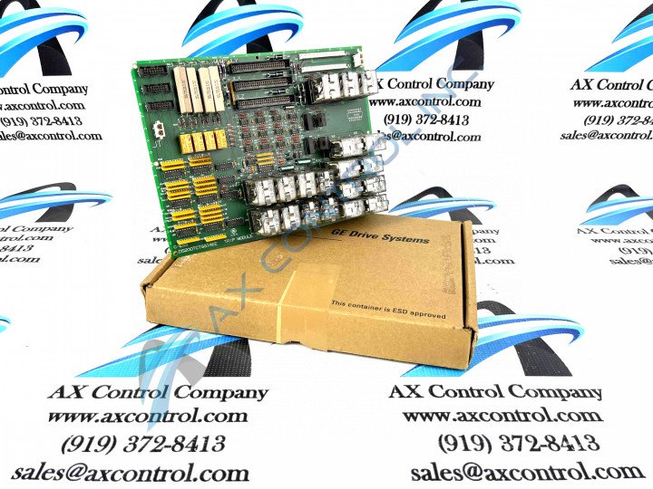
About the DS200TCTSG1
This DS200TCTSG1 printed circuit board was originally manufactured by General Electric, for placement in the Mark V Series of Turbine Control Systems, as mentioned previously. The Mark V Series that this DS200TCTSG1 PCB belongs to is classifiable as a legacy product series, due to its eventual manufacturing discontinuation in the many years following its initial release. While a legacy product series, this DS200TCTSG1 Board's Mark V Series is additionally definable as one of the final General Electric product series to make use of the respected automated industrial retailer's final Speedtronic control system technology-incorporating product series, utilizing the same control system technology first introduced to the automated industrial sphere with the release of the Mark I Series in the mid to late 1960s. This DS200TCTSG1 printed circuit board is defined in available Mark V Series instructional documentation referred to as a Simplex Trip Board boasting a normal Mark V Series product assembly. This DS200TCTSG1 PCB's simple functional status is reinforced by its possession of no singular functionality or artwork-altering product revisions, as defined through its DS200TCTSG1 functional product number's concerted lack of any trailing revision-indicating digits.
Hardware Tips and Specifications
This DS200TCTSG1 printed circuit board product offering's intended function as a Simplex Trip Board is introduced through a series of functionality-inducing hardware components. For starters, it is likely that this DS200TCTSG1 product runs using a Simplex redundancy style, as indicated in its full functional product description. The GE Simplex Trip Board DS200TCTSG1 is populated with 12 plug-in relays. It also has 3 16-pin connectors and 2 12-pin connectors. The IDs assigned to the 16-pin connectors are JDR, JDS and JDT. The IDs assigned to the 12-pin connectors are JN and JM. The GE Simplex Trip Board DS200TCTSG1 is populated with multiple relay sockets. The relay sockets enable the installer to attach the signal wires for the 12 relays. That is, the circuits controlled by the relays are attached to the board through the relay sockets. Insert the bare copper wires into the terminals. The relay sockets use quick connect terminals. Unfortunately, this DS200TCTSG1 product offering is not well-detailed in available General Electric instructional manual materials; most likely a function of its placement in a now-obsolete legacy product series. With this being true, the DS200TCTSG1 functional product number becomes a central source of original hardware and hardware specification information for this DS200TCTSG1 product, beginning with its initial DS200 series tag holding dual naming responsibilities. This DS200TCTSG1 functional product number's DS200 series tag exposes the DS200TCTSG1 PCB to be a normal-assembly Mark V Series product with a domestic original manufacture location. Some of the other important hardware details revealed in the DS200TCTSG1 functional product number include this DS200TCTSG1 device's:
- TCTS functional product abbreviation
- Group one Mark V Series product grouping
- Absence of any significant product revisions
When you replace the board mark on the signal wires where they are connected on the relay socket so you’ll know where to reconnect them on the replacement board. The terminals have IDs that you can use to know where the signal wires are connected. The DS200TCTSG1 board is also populated with 4 50 VDC capacitors. The capacitors store and release current during normal operations. When you remove the board, turn off the power to the drive and wait 30 seconds before you touch the board. This gives time for the current in the capacitors to exit the drive. The IDs for the 2 12-pin connectors are JN and JM. When you first install the board, the information that comes with the board explains which ribbon cables to attach to the 12-pin connectors. Once the board is installed, use the IDs to identify where to attach the cables after you reinstall the board or install a replacement board.


