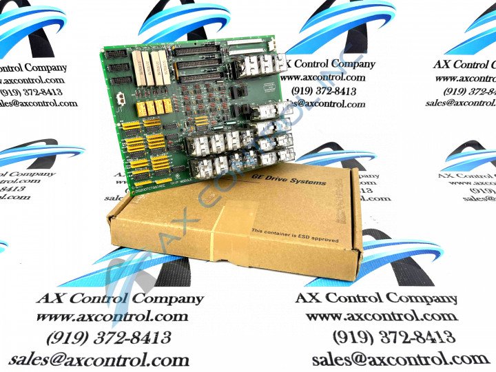
About the DS200TCTSG1A
This DS200TCTSG1A printed circuit board was manufactured for the Mark V Turbine Control System Series of respected industrial retailer General Electric, as revealed above. This DS200TCTSG1A printed circuit board or PCB for short is describes in original General Electric instructional manual literature as a Simplex Trip Board or Simplex Trip Card, although it is not considered the original Mark V Series product with its functionality. The original Simplex Trip Card that was manufactured for the Mark V Turbine Control System Series was the DS200TCTSG1 parent printed circuit board missing this DS200TCTSG1 device's singular A-rated functional product revision. Before making a purchase decision on this DS200TCTSG1A PCB, it is important to understand that this product's singular functional revision may alter the originally-introduced performance specifications and dimensions of the Mark V Series DS200TCTSG1A Simplex Trip Card greatly.
Hardware Tips and Specifications
This DS200TCTSG1A Simplex Trip Board plays a specific functional role within its greater Mark V Turbine Control Series, which means it comes equipped with its own specific series of hardware components and component specifications as well. The GE Simplex Trip Board DS200TCTSG1A is populated with 12 plug-in relays. It also has 3 16-pin connectors and 2 12-pin connectors. The IDs assigned to the 16-pin connectors are JDR, JDS and JDT. The IDs assigned to the 12-pin connectors are JN and JM. The IDs assigned to the plug-in relays begin with the letter K; the letter K usually being followed with a number. For example, some identifiers are K1, K5, and H12. This DS200TCTSG1A Mark V Series product offering is a Mark V Series Group 1 product; the Mark V Series grouping with the highest number of component circuit boards, and possesses a normal style of Mark V Series circuit board assembly, including a thick protective layer of PCB coating.
When a relay stops functioning in the assembly of this DS200TCTSG1A PCB, it can be replaced, although instructions embedded in original Mark V Series manuals must be followed in lieu of potentially dangerous surface voltages. To replace a relay on the DS200TCTSG1A PCB, first remove power from the drive. Once power is off, disconnect the cables and remove the screws that secure the board; you will need another person to hold the board while the screws are removed. Use 2 hands to carefully remove the board from the drive. The wire retention clips snap off the bottom of the connector. Swing it back from the relay, and then grab the relay with 1 hand and pull up to remove the defective relay. Align the replacement with the connector and press down to install it. Swing the retention wire over the relay and use 1 hand to lock it under the connector. AX Control recognizes the static-sensitive nature of this DS200TCTSG1A PCB during shipping, and will package this board in a resistant insulated plastic bag with additional foam insulation for shipping.


