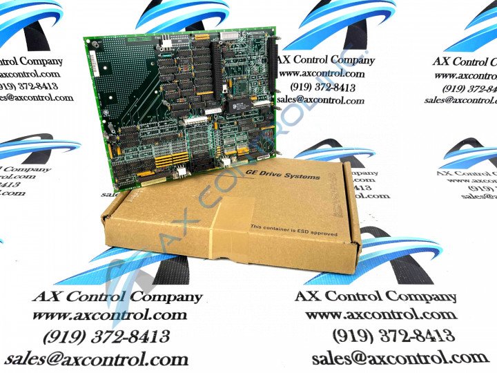
About the DS200UCIAG1ACB
This DS200UCIAG1ACB UC2000 Motherboard product offering was, as mentioned previously, manufactured by trusted automated industrial supplier General Electric, specifically for placement in their Mark V Speedtronic Turbine Control System Series. As you might have been able to deduce from its full extended series name, the Mark V Series that this DS200UCIAG1ACB functional product offering belongs has crucial applications in the control and management systems of popular and compatible General Electric wind, steam, and gas turbine automated drive assemblies. The Mark V Series that this DS200UCIAG1ACB printed circuit board product offering belongs to is additionally definable as one of the final General Electric series to make use of their patented Speedtronic control system technology first seen alongside the release of the Mark I in the late 1960s. Finally, this DS200UCIAG1ACB printed circuit board's greater Mark V Series has to be classified as a now-obsolete legacy product series, given its eventual manufacturing discontinuation taking place in the numerous years following its initial release. While this DS200UCIAG1ACB printed circuit board product is definable as a UC2000 Motherboard in its own right, the originally-produced Mark V Series device of this specific functionality would be the DS200UCIAG1 parent UC2000 Motherboard notable not utilizing any of this DS200UCIAG1ACB product's three significant product revisions.
Hardware Tips and Specifications
This DS200UCIAG1ACB Mark V Series product's Motherboard functionality is introduced alongside its internal assembly's necessitation of a specific grouping of hardware components. The GE UC2000 Motherboard DS200UCIAG1ACB features one microprocessor and multiple PROM modules. It also contains 1 block of 10 LEDs and 2 50-pin connectors. The GE UC2000 Motherboard DS200UCIAG1ACB also is populated with 1 jumper and 1 connector to support the attachment of other boards.The board can be connected to a daughter card that provides additional processing functions. Two daughter cards are optional devices and the choice depends on the additional processing you need. One daughter card provides additional processing with use of a microprocessor. It also supplies additional memory with a memory connector. The memory connector supports 1 memory DIMM for large amounts of additional memory space. The other daughter card provides additional turbine control through the specific components that populate the board. Both daughter cards connect to the board through modular connectors that supply the electrical connections and control signals. The daughter cards rest on standoffs that support the cards. Four screws are used to secure the cards to the standoffs.
Given the fact that this DS200UCIAG1ACB PCB is functionally-defined in its original Mark V Series instructional manual materials as a UC2000 Motherboard, it is a bit surprising to notice that its DS200UCIAG1ACB functional product number asserts a normal Mark V Series assembly version. The DS200UCIAG1ACB functional product number can be considered a strong source of DS200UCIAG1ACB Board hardware component and component specification information, coding for different DS200UCIAG1ACB Board details in specific functional chunks. The DS200UCIAG1ACB functional product number begins with the DS200 series tag dictating its normal Mark V Series assembly version and its domestic original manufacture location. Some of the other relevant DS200UCIAG1ACB Board details revealed in the DS200UCIAG1ACB functional product number include this DS200UCIAG1ACB PCB's UCIA functional product abbreviation, its group one Mark V Series product grouping, its A-rated primary functional revision, its C-rated secondary functional revision, and its B-rated artwork configuration revision. The PROM modules are connected to the DS200UCIAG1ACB board through modular-type sockets that populate the board. Always protect the PROM modules from static build up by wearing a wrist strap. The modules can be removed from the sockets by inserting a flat-blade screwdriver between the socket and the module on the ends of the modules. Gently rock the blade to disconnect the module from the socket. Then, insert the blade on the other end and perform the same action. Immediately place the module in a static protective bag or install the module in the replacement board.


