About the DS200UCIBG3
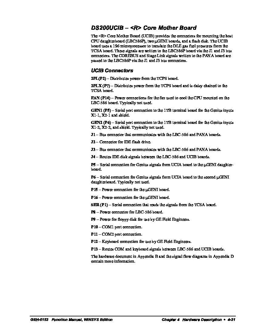
This General Electric Mark V Series product is attributable both as a UC2000 Motherboard and as a R Core Motherboard, based off of both of the functional descriptions that this product is assigned in original Mark V Series instructional manual materials. The official functional description for this DS200UCIBG3 product is that as a R Core Motherboard, and it exists as the original unrevised product manufactured for GE's Mark V Turbine Control System Series. While credited as a Motherboard in its official functional description, this DS200UCIBG3 PCB is slated as not possessing any sort of special assembly version, denoted by the inclusion off the regular DS200 series tag in the DS200UCIBG3 alphanumeric part number. This DS200UCIBG3 Motherboard Device is crucial to the Mark V Series automated drive assembly as it is the source of several connectors for CPU daughterboard mounting purposes.
Hardware Tips and Specifications
To achieve a functional status as an R Core Motherboard, this DS200UCIBG3 printed circut board makes several interesting and unique hardware adoptions and specification choices. The GE UC2000 Motherboard DS200UCIBG3 features one microprocessor and multiple PROM modules. It also contains 1 block of 10 LEDs and 1 50-pin connector. The GE UC2000 Motherboard DS200UCIBG3 also is populated with 1 connector to support the attachment of other boards and 2 3-pin connectors.
The block of LEDs on the DS200UCIBG3 R Core Motherboard provides the operator with a quick assessment of the health of the board. If an error is found, these LEDs flash a numerical code for the error number. However, if no errors are found, the LEDs flash one after the other from left to right. The LEDs are visible from the board cabinet while the drive is operating. If you find that an error is found, there are several steps to take to identify the error, isolate the problem, and potentially repair the board. The board has test points that enable you to test the multiple circuits on the board, although only a qualified servicer has the training and equipment needed to use the test points. The testing device must be properly calibrated for the purpose and also all settings on the tester must be set correctly. Any DS200UCIBG3 diagnostic board testing must be performed when power is removed from the board and the board is removed from the drive and is placed on a clean, dry, and sturdy work surface. A stub ribbon cable is connected to the board and it provides a means to transmit and receive signals; this ribbon cable is permanently attached to the board. Also permanently attached to this DS200UCIBG3 PCB is the J1-labeled hardware jumper, which is manually moveable for the selection of this device's clock enabling. All of the aforementioned hardware components in the assembly of this DS200UCIBG3 printed circuit board should receive at least rudimentary protection from this PCB's normal style of PCB coating.


