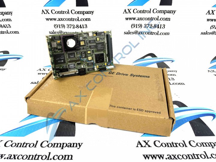
About the DS200UCPBG6AFB
This DS200UCPBG6AFB printed circuit board product offering from General Electric was, as originally mentioned above, manufactured by General Electric, specifically for placement in their Mark V Turbine Control System Series automated drive assembly within the specific functional product role of an IO Engine CPU Board. This DS200UCPBG6AFB printed circuit board or PCB for short's greater Mark V Series is one of the final General Electric Mark product series to make use of their patented Speedtronic control system technology first utilized during the rollout of the Mark I Series in the later 1960s. While this DS200UCPBG6AFB IO Engine CPU Board's greater Mark V Turbine Control System Series may be updated in terms of its control system technology, it is generally considered an obsolete legacy product series due to its eventual manufacturing discontinuation which took place in the many years stemming from its initial series release. This DS200UCPBG6AFB has a normal Mark V Series assembly version, although it has been altered through its assembly's acceptance of three significant product revisions including two functional product revisions and a singular artwork configuration revision. The original Mark V Turbine Control System Series product of this DS200UCPBG6AFB PCB's IO Engine CPU Board functionality is the DS200UCPBG6 parent printed circuit board.
Hardware Tips and Specifications
This DS200UCPBG6AFB PCB's Mark V Series functionality is introduced through the inclusion of a specific set of hardware components. The GE PC Board DS200UCPBG6AFB features one microprocessor and multiple programmable read-only memory (PROM) modules. It also contains 1 dual in-line memory module (DIMM) connector and 1 switch block with 7 switches. It also features 1 34-pin connector and 1 connector for attachment to another board. In terms of voltage suppression, this DS200UCPBG6AFB printed circuit board product offering's voltage regulations are handled by a standard adoption of various Mark V Series-known voltage-limiting hardware components, including different styles of capacitors, resistors, and diodes. This DS200UCPBG6AFB PCB interface to other Mark V Series products through a series of connectors attached to its external ports. Each one of these connectors, as with any hardware component in this DS200UCPBG6AFB Board's assembly, is accompanied by its own factory-printed nomenclature for convenient and fast DS200UCPBG6AFB connector identification. Some of this DS200UCPBG6AFB PCB's connectors include:
- The ARCNET STCA Board COREBUS Connector
- The COM1 STCA Board R Core Monitoring Connector
- The COM2 Connector
- The J1 STCA Board Bus Connector
- The J2 STCA Board Bus Connector
- The IDE Connector
Each of the previously-listed connectors in the assembly of this DS200UCPBG6AFB product have been named through a combination of their specific factory-printed nomenclature lable, their Mark V Series interfacing compatibilities, and their specific application. The COM2 and IDE Connectors have not been named as such as they exist as vestigial structures not meant to be accessed during normative function of the DS200UCPBG6AFB Board.
The PROM modules in this DS200UCPBG6AFB PCB's assembly store the firmware and programming instructions used by the microprocessor. To ensure that the microprocessor functions that same in the replacement GE PC Board DS200UCPBG6AFB the best practice is to use the same level of firmware and programming instructions. When you receive the replacement board, it comes without PROM modules in the sockets. The solution is to insert the PROM modules from the old board into the replacement board. Hand tools are available that are made specifically for removing and inserting PROM modules. One factor to remember is that the PROM modules are damaged by the presence of static on the board. There are some actions you can take to eliminate the presence of static. Keep the board in the sealed ESDs protective bag until just before you install it. Best practice to also keep it in the cardboard box in which it was shipped to you. When you are ready to install it, attach a wrist strap to your arm or hand and connect the other end to a metal surface. This might be a desk leg or workbench support. The metal has to be free of paint or other coverings. Open the bag with a sharp edged tool and place it directly on top of the bag after you flatten out the bag.


