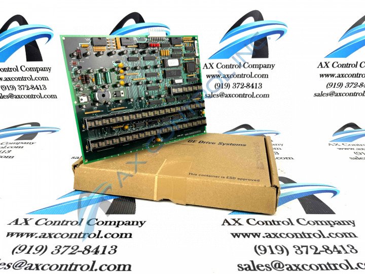
About the DS200UDSAG1AAA
As briefly explained in the DS200UDSAG1AAA product description inserted above, this DS200UDSAG1AAA Excitation Turbine Board was originally manufactured by General Electric, for specific placement in their Mark V Turbine Control System Series. As you can probably tell based off of its full extended series name, the Mark V Series that this DS200UDSAG1AAA printed circuit board or PCB for short belongs to has specific applications in both the management and control systems of popular and compatible wind, steam, and gas turbine automated drive assemblies. With this DS200UDSAG1AAA PCB's Mark V Series' possible alternative energy applications exisitng, it must generally still be considered a now-obsolete legacy product series, as it was discontinued for production by General Electric in one of the many years past its initial rollout. While the Mark V Series is a legacy product series, it is still considered quite the desirable product series on the automated industrial marketplace, as it exists as one of the final developed GE product series to make use of their patented Speedtronic control system technology first seen with the release of the Mark I Series. This DS200UDSAG1AAA printed circuit board product offering is not the original device of its specific Mark V Series functionality; that would be the DS200UDSAG1 parent PCB missing all three of this DS200UDSAG1AAA Device's three significant product revisions.
Hardware Tips and Specifications
As with any Mark V Series printed circuit board made available to our extended new and reconditioned inventory here, this DS200UDSAG1AAA PCB's specific functional role is introduced with its normal assembly's acceptance of a specialized series of hardware components and component specifications. The GE Excitation Board DS200UDSAG1AAA features one 1 80196 microprocessor and several erasable programmable read-only memory (EPROM) modules. The GE Excitation Board DS200UDSAG1AAA also is populated with 21 4-character displays and 32 LEDs. The board also features 12 jumpers that are used for configuring the board. Each jumper is assigned an ID that is prefixed with JP and is followed by a number. For example, JP1, JP6, amd JP10 are IDs of jumpers on the board. Each jumper has 3 pins on the board assigned to it. The jumper covers 2 of the pins and the jumper creates a circuit between the 2 pins. The circuit changes the behavior of the board. The pin that is not covered by the jumper is not part of the configuration. This DS200UDSAG1AAA printed circuit board suffers from a lack of originally-printed instructional manual materials online; most likely a symptom of the above-described legacy product series attribution. With this being true, the DS200UDSAG1AAA functional product number can be used as a supplemental source of DS200UDSAG1AAA Board hardware information, coding for specific details in a series of functional naming components. For instance, the DS200UDSAG1AAA functional product number starts off with the dual-functional DS200 series tag indirectly stating its normal Mark V Series assembly and domestic original manufacture location. Some of the other relevant hardware details revealed in the DS200UDSAG1AAA functional product number include this PCB's:
- UDSA functional product abbreviation
- Group one Mark V Series product grouping
- Normal PCB coating style
- A-rated primary functional revision
- A-rated secondary functional revision
- A-rated artwork configuration revision
When the first GE Excitation Board DS200UDSAG1AAA is shipped from the factory, the written instructions describe the configuration options provided by the jumpers. Consulting with the engineers and other parties, the installer selects the options and moves the jumpers to attain the desired results. When the GE Excitation Board DS200UDSAG1AAA is replaced because of failure, configuring the board is much simpler. Use the defective board as a guide and diagram the location of the jumpers. Then, match the jumper locations on the new board. Also, you will notice that the replacement board comes with empty EPROM sockets. Wear a wrist strap when handling EPROM modules. Insert a screwdriver in the end of an EPROM module and lift up to disengage it from the socket. Insert the screwdriver in the other end and lift up to disengage that end. Before making any ultimate purchase decision on this DS200UDSAG1AAA product offering, it is crucial to realize that its originally-introduced performance specifications and dimensions have surely been altered from their base-revised statuses by this DS200UDSAG1AAA PCB's acceptance of a three-fold revision table.


