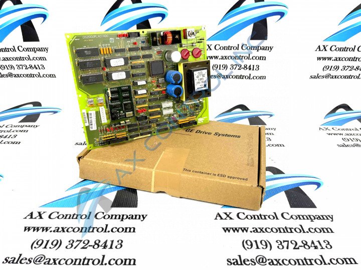
About the DS200UPLAG1
This DS200UPLAG1 LAN Power Supply Circuit Board, as explained in greater detail above, was originally designed and produced by General Electric, specifically for placement in their now-obsolete Speedtronic Mark V legacy product series. This product series is one of the final General Electric Mark product series to incorporate the manufacturer's patented Speedtronic control system technology into its various offerings, although it has been deemed obsolete or legacy due to its eventual manufacturing discontinuation in the many year following its initial release. This DS200UPLAG1 printed circuit board or PCB for short is actually the originally-designed product of its greater Mark V Series intended functionality, as revealed by its DS200UPLAG1 functional product number's absence of any trailing, revision-indicating alphanumeric digits. This DS200UPLAG1 PCB is also a Mark V Series product with a standard assembly version, also as exposed through use of the DS200UPLAG1 GE functional product number.
Hardware Tips and Specifications
As with any General Electric printed circuit board available to our inventory of new and reconditioned products, this DS200UPLAG1 PCB makes use of its own individual series of functionality-introducing hardware components and component specifications. The GE LAN Power Supply Circuit Board DS200UPLAG1 contains two 26-pin connectors, a fuse, and one toggle switch. The board also has one reset button and a single 8-pin connector. The 26-pin connectors on this model are used to send and receive control signals to the other boards and components that control the behavior of the drive. Ribbon cables attach to the 26-pin connectors, and you must consider some guidelines to follow when you remove or install a ribbon cable. Multiple small wires make up the ribbon cable, and each wire carries a signal from the board or to the board that helps control the drive. Always place your thumb and one finger on the connector portion of the cable when you pull the cable out of the connector on the board. If you pull from the ribbon portion of the cable, it puts too much stress on the connector and it could easily cause the wires to be disconnected. When you connect the ribbon cable to the DS200UPLAG1 model, use your thumb and one finger to hold the connector. Align the connector and use pressure to gently connect the cable to the board. Notice that the pins on the connectors are easily bent and so you should check the alignment of the two connectors to prevent the pins from being bent. Other connectors also populate the board, and it is best practice to never pull the cables out from the cable portion.
While the various procedures and strategies necessary for convenient and safe installation of this DS200UPLAG1 product offering are certainly important, their above insertion on this personalized product page is truly more reminiscent of a noted lack of DS200UPLAG1-pertinent original instructional materials on the internet for research purposes. With this in mind, the DS200UPLAG1 functional product number can additionally be considered a strong source of original DS200UPLAG1 Board hardware component and component specification information. Some of the specific hardware details revealed in functional chunks of the DS200UPLAG1 functional product number include this DS200UPLAG1 PCB's:
- Normal Mark V Series assembly version
- Domestic original manufacture location
- UPLA functional product abbreviation
- Normal PCB coating style
- Absence of any functional or artwork revision


