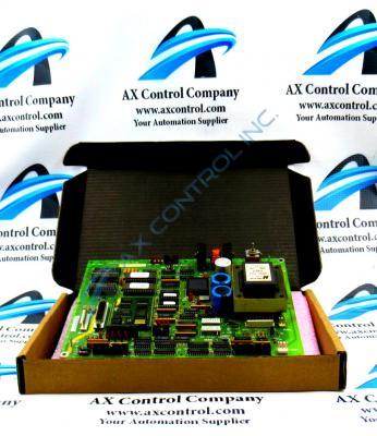
About the DS200UPLAG1ADA
This DS200UPLAG1ADA printed circuit board product offering was originally manufactured and produced by General Electric, specifically for placement in the Mark V Turbine Control System Series as described above. The Mark V Series that this DS200UPLAG1ADA printed circuit board or PCB for short belongs to is self-explanatory, as it exists with specific applications in the control and management systems of popular, compatible gas, steam and wind turbine automated drive assemblies. With this being the case, this DS200UPLAG1ADA product offering's greater Mark V Series must be considered a now-obsolete legacy product series; as its manufacture was discontinued due to obsolescence in one of the many years past its initial release. While a legacy product series, this DS200UPLAG1ADA LAN Power Supply Board's greater Mark V Series is still something of a highly-desired offering on the figurative automated industrial marketplace; as it exists as one of the final-developed Mark product series to utilize General Electric's patented Speedtronic control system technology; a technology first seen with the release of the Mark I Series in the late 1960s.
Hardware Tips and Specifications
As with any printed circuit board product made available to our extended inventory of new and used products here; this DS200UPLAG1ADA PCB's specific functionality is encouraged through its normal Mark V Series assembly's acceptance of a specific series of functionality-inducing hardware components and component specifications. The General Electric LAN Power Supply Circuit Board DS200UPLAG1ADA contains two 26-pin connectors, 1 fuse, and 1 toggle switch. The board also has one reset button and 1 8-pin connector. The reset button on the board temporarily removes power from the board and then restarts it without having to restart the drive or any other boards. If the board appears to be functioning erratically or exhibiting other irregularities, you can press the reset button. This DS200UPLAG1ADA printed circuit board product offering from General Electric is actually not the originally-produced product for its specific Mark V Series functional role; that would be the DS200UPLAG1 parent LAN Power Supply Circuit Board missing this DS200UPLAG1ADA product's full three-fold revision history. Given the fact that this DS200UPLAG1ADA PCB exists as a member of a now-obsolete legacy product series, it is not surrounded by a plethora of pertinent Mark V Series manual materials online. With this being true, the DS200UPLAG1ADA functional product number itself can be considered a primary source of this DS200UPLAG1ADA PCB's hardware information; coding for specific details in a series of consecutive functional naming components. For instance, the DS200UPLAG1ADA functional product number begins with the dual-functional DS200 series tag delegating this DS200UPLAG1ADA PCB's normal Mark V Series assembly as well as its domestic location of original manufacture. Some of the other relevant hardware information revealed through part number includes this DS200UPLAG1ADA Device's:
- UPLA functional abbreviation
- Normal PCB coating style
- Group one Mark V Series product grouping
- Three-fold product revision table
Care must be taken because power is present in the drive when you press the reset button. Only a trained servicer should press the reset button. First, open the board cabinet door and locate the board. Make sure you have a good line of site of all the boards in the cabinet and reach inside the cabinet. Be sure to not touch any components in the cabinet because of the high voltage present in the drive. Any component, solder point, or cable might deliver an electric shock or burn. Use one finger to press only the reset button and avoid touching other components on the board. Press the button for a few seconds, then release it. This is a useful procedure for troubleshooting the board. If you suspect that the board continues to function improperly, remove all power to the drive and remove the board. Use a screwdriver to remove the four screws from the drive and move the board to a static protective surface. Locate the test points on the board and test the circuits.


