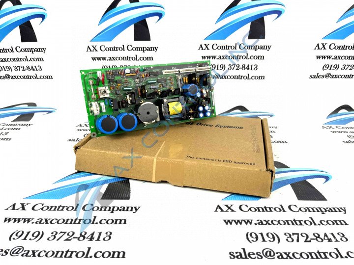
About the DS200UPSAG1
This DS200UPSAG1 printed circuit board product offering from General Electric was originally, as mentioned just above, manufactured specifically for the Mark V Turbine Control System Series; a rather self-explanatory GE product series retaining specific applications in the management and control systems of popular and compatible wind, steam, and gas turbine automated drive assemblies. The Mark V Series that this DS200UPSAG1 printed circuit board or PCB for short belongs to, while pertinent to some newly-developed possible alternative energy applications, has to be considered obsolete as a whole, as it exists as a legacy product series discontinued for manufactured due to obsolescence in one of the many years past its original GE product series release. This DS200UPSAG1 PCB's Mark V Series is not wholly unattractive on the general automated industrial marketplace despite its legacy status; as it exists as one of the final-developed product series to make use of the patented Speedtronic control system technology across a range of its offerings.
Hardware Tips and Specifications
As with any Mark V Series product made available to our extended new and reconditioned inventory here, this DS200UPSAG1 PCB's intended Mark V Series functionality is developed with its normal Mark V Series assembly's introduction of a specialized series of hardware components and hardware component specifications. For starters, any voltage suppression in the normal mark V Series assembly of this DS200UPSAG1 product offering is likely handled by a series-standardized selection of voltage-limiting hardware components including various styles and renditions of diodes, resistors, transistors, and integrated circuits. The GE EX2000 Power Supply Board DS200UPSAG1 features one reset button, 3 fuses, and 1 LED. The GE EX2000 Power Supply Board DS200UPSAG1 also is populated with 3 9-pin connectors, multiple capacitors, and test points. The IDs of the 9-pin connectors on the GE EX2000 Power Supply Board DS200UPSAG1 are 2PLC, 2PLB, and 2PLA. When the original board from the factory is installed in the drive, the purpose of each 9-pin connector is detailed in the printed instructions. Using that information, the installer attaches the ribbon cables to the connectors. In that way the right signals are received by the board from other components. And, the signals are transmitted to the right boards in the drive. When you replace the board because of a defect, it is critical that the 9-pin cables are attached to the same connectors on the replacement board.
First, examine the old board and mark the 9-pin cables with the ID of the connector each cable is attached to. For example, write 2PLC on the cable attached to connector 2PLC. Do the same for each 9-pin connector that is attached to a cable. The 1 LED on the board is lit when the board is receiving power. The LED is green when lit and when off, the LED indicates power is not present. It is important to note that the LED does not indicate that the health of the board is OK. The board might be receiving power but not functioning properly. Use the test points to test the separate circuits on the board. The above-included information on this DS200UPSAG1 personalized product page is overwhelmingly reminiscent of elements available upon a visual inspection of the DS200UPSAG1 Board itself; given this DS200UPSAG1 PCB's legacy series status and its concurrent unavailabity of original instructional documentation. With this lack being identified, the DS200UPSAG1 functional product number itself can act as a supplementary source of DS200UPSAG1 Board hardware information; coding for specific details in a series of consecutive functional naming components. For example, the DS200UPSAG1 functional product number begins with the dual-functional DS200 series tag delegating this DS200UPSAG1 product's normal Mark V Series assembly as well as its domestic original manufacture location. Some of the other relevant detail revealed through the DS200UPSAG1 functional product number includes this DS200UPSAG1 PCB's:
- UPSA functional product abbreviation
- Normal PCB coating style
- Group one Mark V Series product grouping
- Absence of any significant revision


