About the DS215UCVAG3AD
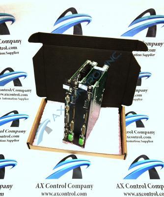
This DS215UCVAG3AD Unit Controller 2000/VME Board was originally manufactured for placement in the Mark V Turbine Control System Series of respected industrial retailer General Electric, as explained above. This DS215UCVAG3AD Unit Controller/VME Board has a special type of Mark V Series assembly version, as represented through the presence of the initial DS215 series tag in its DS215UCVAG3AD alphanumeric product number. In addition to the special assembly version that has been attributed to this DS215UCVAG3AD PCB, it is not considered the original version of Unit Controller 2000/VME Board that was manufactured for the Mark V Series; that's the DS215UCVAG3 parent printed circuit board missing this DS215UCVAG3AD product's two significant revisions.
Hardware Tips and Specifications
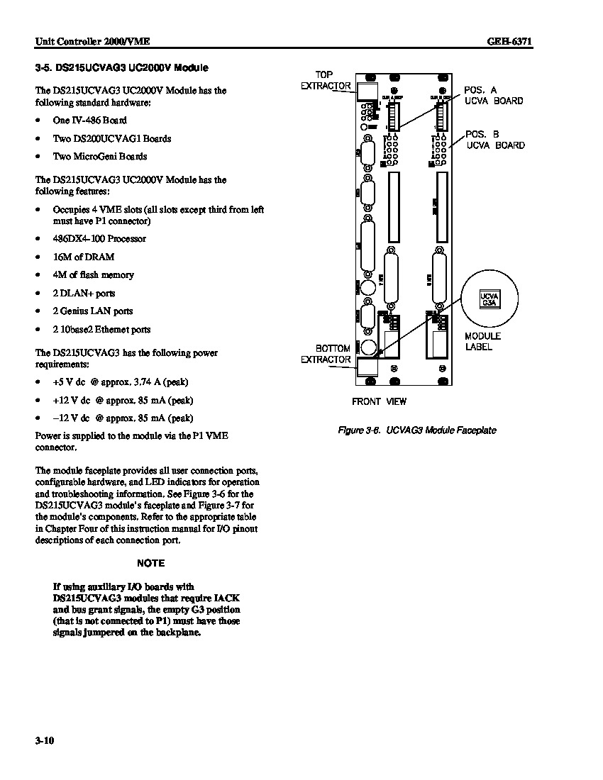
Many Mark V Series product offerings, including this DS215UCVAG3AD Unit Controller 2000/VME Board, necessitate their own specialized series of hardware components and component specifications to achieve their original intended series functionality. The GE Unit Controller 2000/VME Board DS215UCVAG3AD features one Ethernet connector, and multiple LED status indicators. The GE Unit Controller 2000/VME Board DS215UCVAG3AD is also populated with 2 blocks of configuration switches and a connector that enables the attachment to a hard disk drive. The GE Unit Controller 2000/VME Board DS215UCVAG3AD is installed in the VME rack assembly used alongside the Mark V Series. To install the board, align it with the open VME rack slots you plan to install it in and slid it into the rack. The connector on the rear of the board is inserted into the matching connector in the rack. Close the retention levers on the board to secure the board in the rack. The status LEDs are lit shortly after you install the board, if power is available to the rack. The LEDs are green when lit. These aforementioned LEDs are labeled SLOT1, ACTIVE, BACC, ENET, OK, and BERR. The ENET LED is lit when an Ethernet connection is made to a local area network. The LED flashes to indicate activity is taking place on the network.
Connectors are available on the front of the board for attaching the board to a keyboard and monitor. With a keyboard and monitor attached, you can access the user interface and control the operation of the board. The switches on the front of this DS215UCVAG3AD VME board enable the operator to configure the board to the specific requirements of the site. Use the written material supplied with the original board for a description of the switches and how they change the processing activity of the board. Before making a final purchase decision on this DS215UCVAG3AD Unit Controller 2000/VME Board, it is important to consider that this DS215UCVAG3AD PCB is a twice-revised Mark V Series offering, and that with this alteration in mind, its originally-introduced performance specifications and dimensions may have been modified.


