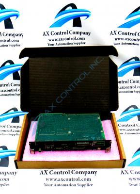
About the DS215UCVBG1AF
Greater Product Series Information
This DS215UCVBG1AF printed circuit board product offering was originally manufactured by General Electric, as mentioned before, for specific placement in their Mark V Turbine Control System Series as a UC2000V Module or a Unit Controller 2000/VME Module. This DS215UCVBG1AF modular assembly device's greater Mark V Series, as you can probably tell by its full extended series name, has specific applications:
- in the management and control systems of popular and compatible wind, steam, and gas turbine automated drive assemblies.
- in a now-obsolete legacy General Electric product series
- it was discontinued for manufacture due to obsolescence in the many years following its initial inception
- aided by the use of their patented Speedtronic control system technology
Before making any final purchase decision on this DS215UCVBG1AF product offering, it is crucial to realize that its originally-introduced performance specifications and dimensions have almost certainly been altered by its special Mark V Series modular assembly's acceptance of two differently-rated functional product revisions.
Hardware Tips and Specifications
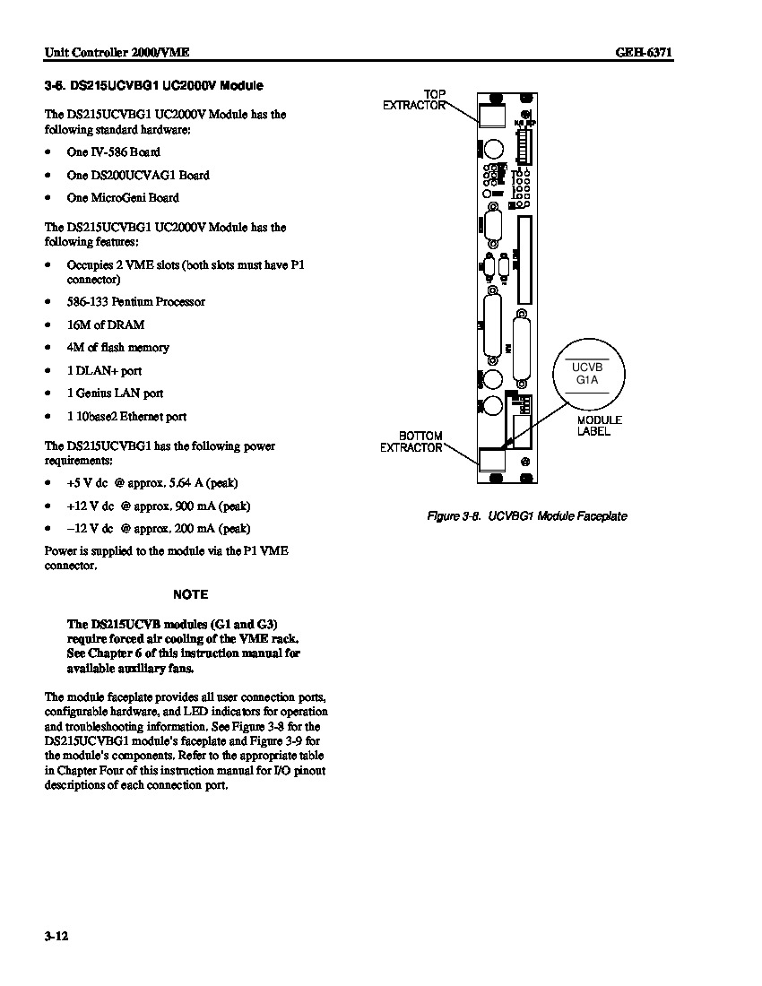
As with any Mark V Turbine Control System Series product available to our new and reconditioned inventory here, this DS215UCVBG1AF device's functionality is introduced with its internal assembly's acceptance of a unique series of hardware components and component specifications. The GE Module Genius Controller DS215UCVBG1AF features:
- one Ethernet connector
- multiple LED status indicators
- 2 blocks of configuration switches
- a connector that enables attachment to a hard disk drive
- connectors that mate with matching connectors at the rear of the rack
- the connectors provide power and signals for the controller
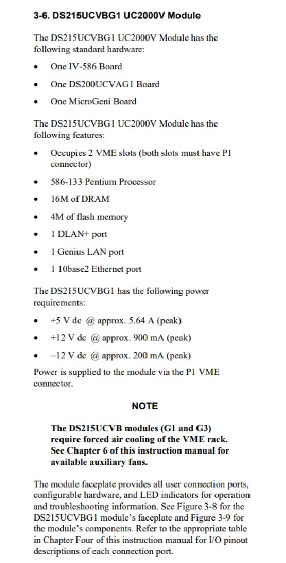
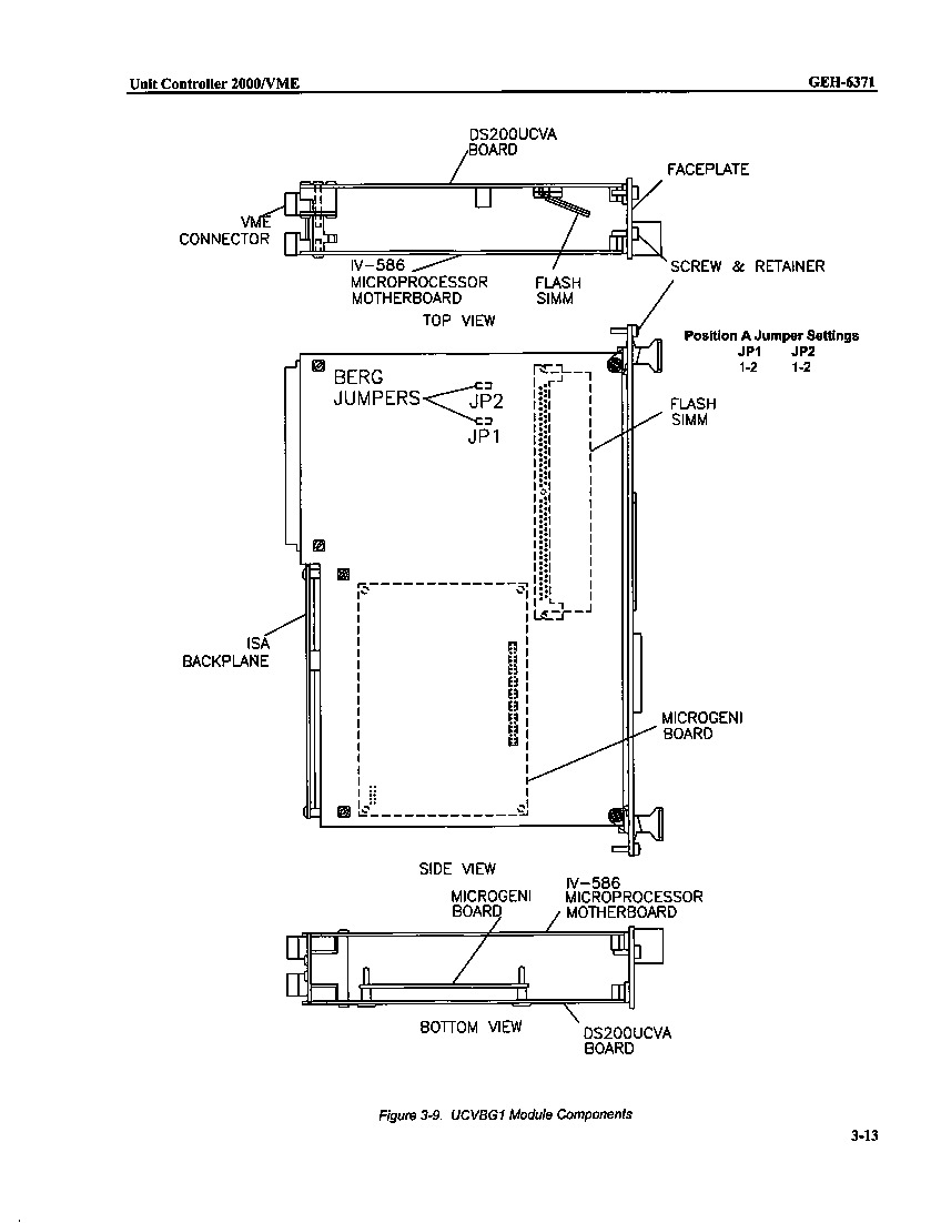
The controller receives signals from other devices and components in the rack. The controller processes the signals and transmits the new signals to other components and devices. The special assembly version of this DS215UCVBG1AF UC2000V Module product offering is most likely introduced by its external assembly's acceptance of three significant Mark V Series daughterboard products, which increase its overall size to demand two slots in its greater Mark V Series VME Rack mounting assembly. Some of this DS215UCVBG1AF PCB's daughterboards include:
- An IV-586 Board
- A DS200UCVAG1 Board
- A MicroGeni Board
DS215UCVBG1AF UC2000V Module LED/Diagnostic Tips
Each of the above-listed daughterboards contributing to the special assembly of this DS215UCVBG1AF product offering have simply been named through the factory-printed nomenclature label they are accompanied by on the base circuit board of this DS215UCVBG1AF device. The DS200UCVAG1 Board is available here at AX Control for repair and replacement, and is considered to exist as a standalone member of the Mark V Series, while this DS215UCVBG1AF product offering's IV-586 and MicroGeni Boards are almost considered to exist more as standard hardware components separate from our catalog. An operator can monitor the processing by viewing status LEDs in the front of the controller. For example:
- the OK LED is lit if the controller passes all checks during startup and is processing successfully
- The ENET LED is lit if the Ethernet network is functioning
- The LED flashes when activity is taking place on the Ethernet network
- A second set of of LEDs are available if an error occurs
- the LEDs display the hex representation of the error code
- this provides the operator with a quick understanding of the error without accessing the troubleshooting tool box
- the tool box is an application available on the controller that list all the errors and warnings on the controller
- the errors are listed in decimal and hex formats
- the tool box also provides an indication of the processing taking place when the error occurred


