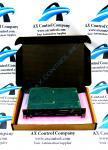
About the DS215UCVBG1AJ
As specified in the brief DS215UCVBG1AJ product description inserted above, this DS215UCVBG1AJ printed circuit board product offering from General Electric was specifically manufactured for a functional placement in their Mark V Turbine Control System Series automated drive assembly as a UC2000V Module. This DS215UCVBG1AJ printed circuit board or PCB for short's greater Mark V Series is something of a self-explanatory General Electric product series, as it exists with a series of set specific applications in the control and management systems of popular and compatible wind, steam, and gas turbine automated drive assemblies. With this being the case, this DS215UCVBG1AJ UC2000V Module's greater Mark V Turbine Control System Series must be considered obsolete as a whole, as it exists as one of the lastly-developed GE Mark product series to feature the patented Speedtronic control system technology across a range of its offerings. The Speedtronic control system technology seen in this DS215UCVBG1AJ Module and its greater Mark V Series was first introduced to the automated industrial landscape with the release of the previous Mark I Series in the later 1960s.
Hardware Tips and Specifications
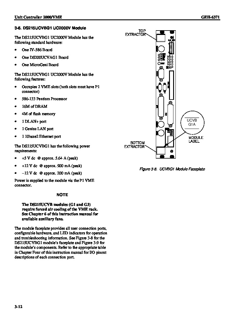
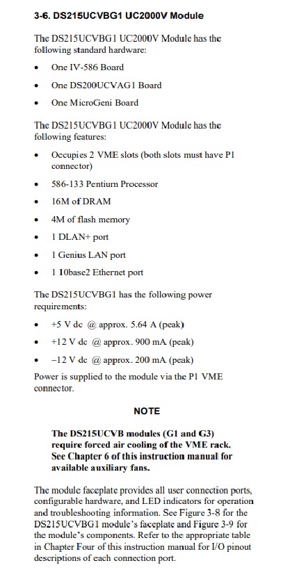
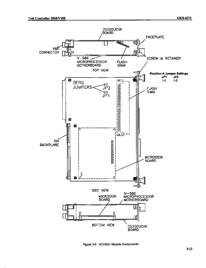
As with any General Electric product made available to our extended new and reconditioned inventory here, this DS215UCVBG1AJ PCB's normal Mark V Series functionality is induced with its special modular assembly's acceptance of a unique series of functionality-inducing hardware selections. The GE Module Genius Controller DS215UCVBG1AJ features one Ethernet connector, and multiple LED status indicators. The GE Module Genius Controller DS215UCVBG1AJ is also populated with 2 blocks of configuration switches and a connector that enables attachment to a hard disk drive. The switches on the panel are used to set the direct local area network dLAN) node number for the controller. The node number values are numbers between 0 and 255. There are 8 switches for the hex number. You can also connect a keyboard and monitor. The keyboard and monitor enable the operator to access the user interface for the troubleshooting tools. The operator can view a log of all the warnings and errors that have occurred. Given the fact that this DS215UCVBG1AJ Module exists as a member of a now-defunct legacy product series, it should be no real surprise to find out that the DS215UCVBG1AJ functional product number can exist as a primary source of DS215UCVBG1AJ Board information; coding for specific details in a series of functional naming segments. For instance, the DS215UCVBG1AJ functional product number begins with the dual-functional DS215 series tag delegating this DS215UCVBG1AJ PCB's special Mark V Series assembly as well as its domestic original manufacture location. Some of the other relevant hardware information revealed in the DS215UCVBG1AJ functional product number includes this Module's:
- UCVB product abbreviation
- Normal PCB coating style
- Group one Mark V Series product grouping
- A-rated primary functional revision
- J-rated secondary functional revision
Another troubleshooting tool are the status LEDs and the indicator LEDs. The status LEDs are a series of LEDs that represent in hex the error codes that have been generated for the controller. It provides the operator with a means to quickly ascertain the error codes without using the troubleshooting toolbox. The indicator LEDs are also on the display panel. View them to understand if the controller is processing as normal. For example, the ENET LED flashes if activity is present on the Ethernet network. The OK LED is lit if the controller is receiving power, is processing as normal, and has experienced no fatal errors. To remove the controller, first open the top and bottom extractor levers. Then, grasp the controller and pull it out of the rack. The rear of the controller is populated with connectors that attach the board to the rack when you slide the controller into the rack.


